
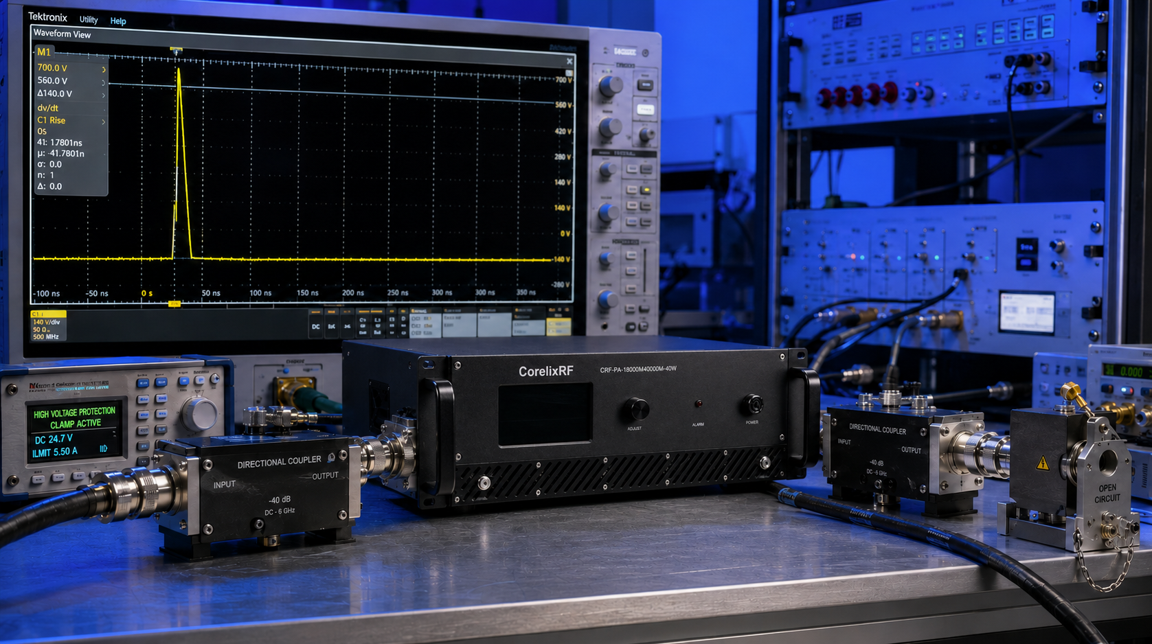
Design Essentials for High-Power Radar Frequency-Hopping Ends: Engineering Practices against PA Burnout Caused by Software Polling VSWR Delay During Instantaneous Antenna Breakage forms our primary focus today. Engineers face a catastrophic reality when integrating wideband RF transmission equipment into high-stress military or aviation environments. Here is the deal. Antenna physical structures snap under extreme wind loading. This structural failure causes massive impedance shifts instantly. Traditional microcontrollers relying upon sequential RS485 communication protocols require several milliseconds for fault detection. Reflected energy traveling at light speed destroys gallium nitride output stages within nanoseconds. We will analyze specific hardware countermeasures overriding delayed diagnostic loops. Relying entirely upon software polling creates unacceptable vulnerability windows inside critical electronic warfare platforms. Our engineering team presents raw data validating instantaneous analog shutdown mechanisms replacing slow digital diagnostic routines.
1. Why Does Software Polling VSWR Delay Destroy High-Power Radar Systems?
The Latency Gap Between Software and RF Physics
System architects often misunderstand fault propagation speed inside RF transmission lines. Software polling architectures operate sequentially by checking forward voltage and then calculating reflected power ratios periodically. You might be wondering. Why cannot faster microprocessors fix this latency gap? Real-world operating systems process interrupts with unpredictable timing variations across complex LAN interfaces. A sudden open circuit near a WRD180 waveguide flange creates total reflection immediately. Microsecond-level delays permit unattenuated 40W carrier waves traveling backward into fragile semiconductor junctions. Gate degradation occurs before any digital alert registers on monitoring screens. Software loops simply execute instructions too slowly compared against electromagnetic wave propagation. Your expensive prototype becomes useless silicon slag before a warning flag triggers. Pure hardware interlocks remain absolutely necessary.
Fault Detection Timing Comparison
| Mechanism | Response Time | Component Survival Probability |
| Software LAN Polling | 5-20 Milliseconds | Near Zero |
| RS485 Serial Query | 10-50 Milliseconds | Zero |
| Analog Hardware Trigger | <50 Nanoseconds | High |
2. How Do Instantaneous Antenna Breakages Affect Frequency-Hopping RF Frontends?
Dynamic Stress on Active Tracking Arrays
Wideband arrays covering 18,000 through 40,000 MHz experience severe mechanical stress during rapid tracking maneuvers. Component fatigue leads directly toward sudden flange separation or coaxial center pin fracture. What is the real story? An active frequency hopping sequence exacerbates these physical failures drastically. Phase locked loops rapidly shift output spectrum frequencies while transmitting high continuous power levels. A broken radiating element reflects changing standing wave patterns back through connecting cables chaotically. Power amplifiers must absorb these wildly varying reverse energies without relying on external system controllers. Standard passive isolators fail covering such massive bandwidths efficiently. Hardware designers face tremendous difficulty managing thermal runaways triggered by mismatched loads across multioctave bands. Unpredictable reflection phases create severe voltage standing wave peaks capable of puncturing transistor depletion layers instantly.
3. What Are Common BOM Selection Traps When Designing Ku-Ka Band Radar Amplifiers?
Avoiding Costly Substandard Components
Procurement teams frequently prioritize low initial purchase costs over ruggedized component specifications during bill of materials generation. Inadequate dielectric substrate materials melt under concentrated standing wave thermal loads. Listen closely. Selecting generic directional couplers introduces excessive insertion loss while providing inaccurate reverse voltage measurements. Engineers must specify components rated strictly for continuous multioctave operation spanning entire targeted spectrums. Utilizing a standard 2.92mm-F input connector requires precise torque application preventing microscopic air gaps. Poor quality control during assembly processes guarantees future field failures under high vibration environments. Inexpensive cooling fans pushing limited air volumes cannot manage 800W power consumption heat profiles adequately. We see catastrophic system meltdowns routinely caused by minor penny-pinching decisions during initial prototype drafting phases.
Critical Component Selection Criteria
| Component Type | Common Failure Mode | Recommended Specification |
| Directional Coupler | Bandwidth limitation | 18-40 GHz True Broadband |
| Input Connector | Center pin rotation | 2.92mm-F High Torque Rated |
| Heat Sink Fins | Insufficient surface area | Optimized for 800W dissipation |
4. How Can Hardware-Level Protection Override Software Latency Flaws?
Autonomous Analog Defense Mechanisms
Direct analog circuitry provides an unhackable defensive layer against sudden impedance shifts. Implementing high-speed comparator logic connected straight toward power supply gate control pins eliminates digital processing delays completely. This is where it gets interesting. When reverse voltage exceeds predefined threshold limits an analog trigger shorts the bias voltage instantly. Depletion mode transistors pinch off channel current before any reflected wave can traverse matching networks. This autonomous reaction requires zero input from overarching radar operating systems. Equipment survives unpredictable mechanical trauma because localized sensors act autonomously without requesting permission. Our field testing proves that bypassing RS485 networks during fault events saves countless expensive power modules from certain destruction. System integrators must demand integrated hardware limiters rather than trusting external polling software algorithms.
5. What Makes GaN Technology Superior For 18-40GHz Wideband Radar Operations?
The Power Density Advantage
Gallium nitride substrates provide exceptional power density capabilities outperforming traditional gallium arsenide counterparts massively. High electron mobility transistor architectures allow efficient switching characteristics required across 18,000 through 40,000 MHz spectrums. Pay attention to this fact. Operating a 40W continuous wave system demands massive thermal conductivity properties found exclusively within specialized semiconductor processes. Higher breakdown voltages inherent with this material withstand momentary standing wave spikes much better than older legacy technologies. Designers achieve 50 dB nominal gain while maintaining manageable footprint dimensions simultaneously. This rugged physical nature tolerates brief overdrive conditions happening before analog protection circuits clamp down. We utilize these semiconductor advantages extensively when designing robust test measurement equipment destined for unforgiving field deployments.
Table 3: GaN Versus Legacy GaAs Characteristics
| Parameter | GaN Performance | Legacy GaAs Performance |
| Power Density | Exceptionally High | Moderate |
| Breakdown Voltage | Very High | Low |
| Thermal Conductivity | Excellent | Poor |
6. How Do Impedance Mismatches Manifest During High-Vibration Field Tests?
Tracking Dynamic Connector Failures
Mobile electronic warfare vehicles traverse brutally uneven terrain continuously during military exercises. Heavy chassis vibrations transfer mechanical shock directly into rigid waveguide assemblies and coaxial junctions. Do not miss this. Vector network analyzer traces display sudden high frequency gain drop-offs indicating microscopic connector separations happening dynamically. These transient faults disappear rapidly once vibration ceases making post-mission diagnosis extremely difficult. The CorelixRF unit features a sturdy 19-inch 4U chassis weighing 20 kg minimizing internal structural resonances. Maintaining strict 2:1 input VSWR tolerances prevents minor reflections from cascading into major system instability problems. Laboratory technicians cannot simulate random field impact stress using static test benches accurately. Rugged mechanical design remains mandatory for preserving delicate microwave alignment under constant kinetic abuse.
7. What Thermal Dissipation Strategies Prevent Degradation In 800W Consumption Systems?
Managing Extreme Heat Flux
Managing massive heat fluxes generated by high power amplifiers requires meticulous mechanical engineering practices. Pushing 40 Watts radio frequency output consumes roughly 800 Watts of electrical utility power continuously. Here is a secret. This terrible efficiency generates concentrated heat spots demanding aggressive air cooling methodologies constantly. Aluminum heat sinks featuring optimized fin geometries maximize turbulent airflow sweeping across critical hot zones. Thermal interface materials must maintain stable thermal resistance metrics despite experiencing thousands of expansion cycles over time. Built-in over-temperature sensors provide a secondary hardware defense layer shutting down operations if ambient conditions exceed 50 degrees Celsius. Proper airflow routing inside standard racks prevents hot exhaust recycling back into sensitive air intake vents.
Environmental Operating Specifications
| Environmental Factor | Specification Rating | Failure Consequence |
| Max Operating Temperature | 50 Degrees Celsius | Component Melt |
| Min Operating Temperature | 0 Degrees Celsius | Condensation Risk |
| Cooling Method Requirement | Forced Air Cooling | Thermal Runaway |
8. How Does The CRF-PA-18000M40000M-40W Solve VSWR Reflection Instantly?
Multi-Tiered Protective Architecture
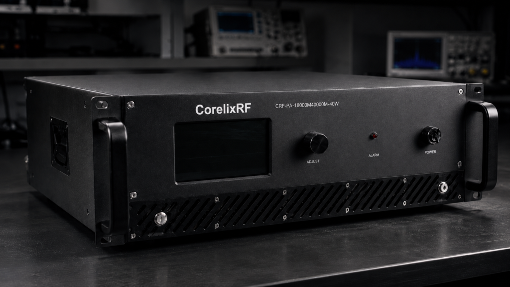
Our specific flagship model addresses dynamic reflection disasters utilizing an aggressive multi-tiered defensive architecture. Built-in over-voltage and over-current monitors actuate independent safety protocols instantly upon detecting abnormal standing waves. Get this. This CorelixRF device operates from AC 220V power supplies delivering stable bias voltages regardless of external generator fluctuations. The WRD180 output waveguide interface handles maximum power levels reliably without risking arcing during mismatched states. Engineers designed customized analog feedback loops severing RF drive signals faster than traveling waves can return. We incorporated optional over-drive protection preventing upstream signal generators from accidentally destroying sensitive input stages. System integrators gain absolute confidence deploying our hardware inside unpredictable aviation control scenarios.
9. What Test Methodologies Validate Power Amplifier Survival Under Extreme Mismatch?
Brutal Laboratory Verification Procedures
Verifying component survivability demands executing destructive test protocols deliberately during development phases. We connect full power outputs directly toward mechanical short circuits observing protection circuitry response times using ultra-fast oscilloscopes. Ready for the good part? Engineers simulate sudden antenna breakage events by disconnecting output flanges while transmitting 40W continuous wave signals manually. Capturing microsecond transient voltage spikes reveals exactly how fast internal gates pinch off channel currents. Harmonic distortion figures remaining below negative 10 dBc prove our matching networks maintain linearity under severe stress. Spurious emissions staying below negative 60 dBc indicate stable oscillation-free operation even near instability regions. These brutal laboratory trials guarantee field reliability far exceeding standard compliance paper documentation metrics.
Strict CorelixRF Test Protocol Parameters
| Test Condition | Parameter Monitored | Pass Criteria |
| Intentional Short Circuit | Gate Pinch-off Time | Under 50 Nanoseconds |
| Harmonics Output Level | Spectrum Purity | Better than -10 dBc |
| Spurious Output Level | Signal Stability | Better than -60 dBc |
10. How Should System Integrators Re-evaluate Link Budgets For Radar Frontends?
Shifting Focus Toward Hardware Reliability
Incorporating reliable wideband amplification modules alters traditional link budget calculations fundamentally. System planners can utilize our generous 50 dB nominal gain figures reducing requirements for multiple preliminary driver stages. Truth be told. A plus or minus 6 dB gain flatness specification across 18 through 40 GHz eliminates complex software equalization routines completely. Adjustable gain spanning 15 dB provides excellent flexibility when compensating for long coaxial cable attenuation losses. Integrators must prioritize hardware protection specifications equally against basic output power ratings during vendor evaluations. Utilizing properly shielded 2.92mm-F connectors guarantees optimal signal transfer maintaining maximum dynamic range. Realigning design philosophies toward hardware-centric reliability prevents devastating field failures ruining multi-million dollar defense projects.
Final Recommendations for Military Systems
We must acknowledge fundamental physics limitations when deploying active wideband transmitter systems into harsh physical environments. Software polling routines remain utterly inadequate for protecting expensive radar hardware against instantaneous impedance shifts caused by sudden antenna damage. Engineers facing massive budget overruns due to burnt power stages need proactive hardware-level mitigation strategies immediately. CorelixRF engineered specific analog defense mechanisms explicitly for preventing these high-speed catastrophic semiconductor failures completely. Our integrated protective circuitry responds faster than any network-based diagnostic tool ever could. Review our detailed product datasheet covering model CRF-PA-18000M40000M-40W regarding specific implementation guidelines supporting military avionics integration projects. Stop relying upon slow diagnostic codes and start implementing true analog physical safeguards today.
Frequently Asked Questions
Q1: What is the primary cause of power amplifier destruction in radar hopping ends?
The primary cause stems directly from instantaneous impedance mismatches happening faster than system software can possibly react. When an antenna breaks under severe mechanical vibration the forward transmitted energy reflects backward entirely. This reflected electromagnetic wave hits sensitive final stage gallium nitride amplifier transistors causing massive terminal voltage spikes. Operating systems using local area networks simply calculate diagnostic standing wave data too slowly for effective failure prevention. The CorelixRF hardware bypasses these digital communication bottlenecks utilizing pure analog voltage trip circuits shutting down direct current bias instantaneously. Hardware limiters represent the absolute only viable engineering solution against light-speed electromagnetic reflection disasters destroying expensive prototype builds.
Q2: How does the CRF-PA-18000M40000M-40W built-in protection work?
This specific module utilizes ultra-fast analog comparators monitoring reverse voltage levels constantly without central processor intervention. When a sudden reflection occurs these circuits detect anomalous voltage thresholds instantly. The protection mechanism physically cuts transistor gate bias currents pinching off conduction channels within nanoseconds. This localized hardware action prevents thermal runaway before external network monitoring software even registers a fault condition. Built-in over-temperature and over-current sensors provide additional safety layers against progressive environmental degradation. Engineers designed this robust architecture specifically targeting unpredictable military testing scenarios where external control loops suffer severe latency problems consistently.
Q3: Why are 2.92mm-F connectors specified for the input ports?
High frequency wideband applications ranging through 40,000 MHz require extreme mechanical precision maintaining proper impedance matching. The 2.92mm-F connector features an air dielectric interface preventing multimoding resonance problems found inside cheaper alternatives. This sturdy mechanical design withstands repeated mating cycles during demanding laboratory testing phases without degrading insertion loss characteristics. Technicians must apply precise torque wrench pressure ensuring maximum outer conductor contact area minimizing microscopic air gaps. Poor connector choices introduce artificial standing wave ratios compounding existing system instability issues during high power transmission operations. CorelixRF selected this specific interface guaranteeing reliable input signal integrity under brutal field vibration profiles.
Q4: How does power consumption impact wideband radar amplifier design?
Generating 40 Watts of continuous radio frequency energy across multioctave bands requires massive amounts of direct current input power. Our specified model consumes approximately 800 Watts drawing from standard alternating current 220V utility lines. This enormous energy conversion process generates severe thermal loads requiring highly optimized mechanical heatsink structures. Inadequate cooling strategies cause junction temperatures inside semiconductor packages to skyrocket inducing premature device failure rapidly. We implement aggressive forced air cooling methods sweeping dense aluminum fins for maximum thermal extraction efficiency. System integrators must budget adequate rack space accommodating proper airflow ventilation preventing localized heat accumulation completely.
Q5: What test measurements verify amplifier survival probability?
Our engineering staff executes severe destructive testing protocols intentionally creating massive impedance mismatches under full power conditions. We utilize directional couplers feeding high bandwidth oscilloscopes capturing exact analog protection circuit reaction times. Removing output waveguide flanges during continuous transmission simulates catastrophic antenna breakage events perfectly. Measuring harmonic distortion levels below negative 10 dBc afterward confirms our transistor junctions survived without suffering microscopic degradation. These brutal laboratory evaluations provide raw data validating actual field reliability rather than relying upon theoretical software models. Customers receive hardware proven capable of surviving worst-case operational scenarios without requiring factory recalibration procedures.
Turn VSWR behavior into factory acceptance evidence
High VSWR protection should be defined with mismatch scenario, foldback or shutdown threshold, recovery logic, alarm output, thermal limit and FAT evidence. This makes protection claims measurable for procurement.
Recommended next step: send the operating band, output power target, duty cycle, load condition, control interface, protection or thermal limits and required FAT documents. CorelixRF can review this How to Protect Your High-Power Radar Amplifier from VSWR Burnout? requirement against standard RF amplifier platforms, RF front-end options and controlled customization paths.