
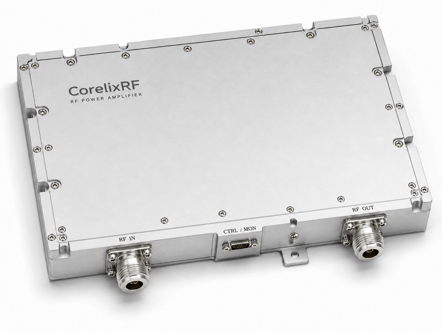
Radar frequency hopping scenarios expose raw engineering reality directly. Software polling delay causes instant amplifier destruction when an antenna breaks abruptly. Our hardware-level protection eliminates such fatal latency permanently. Over twenty years of troubleshooting RF field failures validate this specific approach. We build resilient systems using reliable CorelixRF physical architecture exclusively.
What Causes Instant Amplifier Burnout During Antenna Breakage?
The reality of radar frequency hopping
Agile radar platforms operate under extreme stress constantly. Antennas face physical trauma from high-vibration environments continuously during deployment. A sudden fracture reflects maximum RF energy backward immediately toward sources. This reflected power hits output transistors without mercy or delay. Mobile systems experience physical damage frequently across harsh operational theaters.
Antenna fracture mechanics
Physical breakage alters characteristic impedance instantly across transmission lines. You might be wondering. An open circuit creates infinite voltage standing wave ratio conditions. Reflected waves compound with forward waves catastrophically near active junctions. Peak voltage limits inside transistor dies exceed safe margins rapidly. Dielectric breakdown follows within mere microseconds destroying expensive semiconductor materials.
Software polling latency traps
Standard system architectures rely upon software microcontrollers heavily for monitoring. These digital chips read system sensors periodically during normal operation. A polling loop requires milliseconds for complete execution sequences. Microwave destruction requires only nanoseconds practically speaking. The amplifier burns before any alarm triggers on a monitoring dashboard. Software logic operates far too slowly for high-power microwave defense. System integrators often underestimate transient event speeds dangerously during design phases. They program microcontrollers expecting sequential predictable fault handling. A microcontroller reads forward power first. Next it measures reflected power accurately. Finally mathematical operations calculate actual system VSWR values. Such calculations waste precious time during a sudden hardware crisis. Your screen flashes warnings long after physical smoke appears. Engineers find charred circuit boards upon opening damaged chassis covers. We see this exact failure pattern repeatedly in mobile radar units. Pure software loops offer zero real protection against immediate physical faults.
Why Do Traditional VSWR Protection Schemes Fail Here?
Analog versus digital loops
Many designers implement digital feedback paths blindly without considering speed. Digital converters require multiple clock cycles for basic data acquisition. Analog comparators react based strictly upon raw voltage thresholds. Hardware gates trip unconstrained by arbitrary digital clock speeds. Here is the deal. We trust analog paths when nanoseconds dictate survival.
Thermal runaway timelines
Reflected energy converts directly into localized heat within active regions. Transistor channel temperatures spike exponentially during severe mismatched conditions. Thermal mass cannot absorb such rapid concentrated energy spikes. Software controls try cutting primary power far too late. Gallium nitride structures melt physically under sustained high VSWR events. Copper flanges cannot extract heat fast enough during complete reflection.
Directional coupler limitations
Standard couplers exhibit specific coupling bandwidth constraints inevitably. Coupler directivity degrades across wide operational frequency spans. False readings confuse microcontroller monitoring logic easily under stress. Poor directivity masks true reflection magnitude from primary system sensors. Software cannot protect what poor sensors fail reporting accurately. An entire transmitter chain falls victim alongside bad analog data. We must fix detection methods before patching control algorithms. Every millisecond wasted analyzing bad data guarantees permanent hardware death. You cannot patch basic physics using regular firmware updates. System resets cannot un-burn a melted GaN transistor die. Field technicians replace expensive modules while mission capability drops completely. Radars require continuous uptime during active military deployment operations. Traditional protection delays compromise entire platform operational readiness immediately. Your upstream logic board keeps sending dangerous drive signals blindly. A powerful output stage turns into an internal space heater quickly. We design protection circuits operating completely independent from host CPUs. Local hardware shuts down bias currents autonomously preventing disaster.
| Specification | Software Polling | Hardware Analog |
| Reaction Time | >50 milliseconds | <1 microsecond |
| CPU Dependency | High | Zero |
| Survival Rate | Low | Maximum |
| Implementation | Firmware Code | Physical Circuit |
How Does Hardware-Level Matching Prevent Catastrophic Failure?
Defining hardware-level VSWR defense
True protection requires embedded analog decision making capabilities. High-speed Schottky diodes detect reflected envelope voltages instantly upon mismatch. These analog signals feed direct comparator circuits locally without processing. A tripped comparator kills active gate bias without asking permission. But here is the kicker. No code executes during this critical survival sequence.
GaN transistor ruggedness
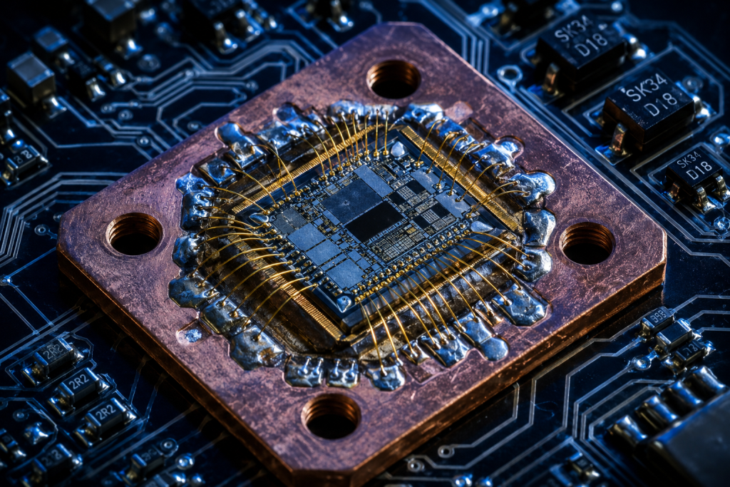
We select active components featuring high breakdown voltages inherently. Gallium Nitride technology survives brief mismatched transients better than older silicon. Inherent transistor toughness buys critical time for our analog shutdown. CorelixRF engineers pair rugged semiconductors with rapid shutdown paths deliberately. This specific combination handles severe operational abuse reliably under fire. Transistor drain nodes withstand doubled voltage swings momentarily.
Eliminating the software middleman
Removing microcontrollers from primary shutdown paths reduces failure points significantly. We route emergency protection signals directly toward RF switch controls. The input RF drive drops immediately before output stages fail. A local physical latch holds this safe state securely indefinitely. Technicians must physically reset equipment after fault clearance verification. Hardware control eliminates unpredictable software interrupt delays entirely from equations. We guarantee module survival regardless of external host system states. Real engineering solves root causes rather than merely masking symptoms. Hardware selection dictates final reliability far beyond superficial software features. Complex firmware often introduces hidden bugs causing unexpected protection failures. Our discrete analog layout remains verifiable using standard laboratory oscilloscopes. You can trace every single protection path visually across PCBs. Transparency builds confidence among senior radar architecture design teams.
What Are The Specific Parameters Of The CRF-PA-2000M8000M-100W?
Wideband frequency coverage
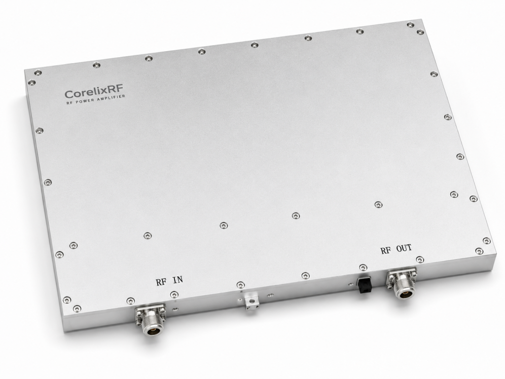
This specific amplifier covers 2,000 through 8,000 MHz continuously. Radar frequency hopping sequences utilize this massive bandwidth seamlessly. You do not need multiple narrow modules anymore. One single RF module handles varied spectral assignments easily. Wideband design simplifies entire transmitter architectures remarkably reducing component counts.
Power and gain metrics
The unit delivers 100 W rated output power consistently. Small signal gain measures exactly 50 dB typically. Gain flatness remains within a tight negative 4 dB window. We provide twenty decibels of adjustable gain control internally. Such precise control aids complex radar link budget alignments directly.
Embedded protection logic
Our design includes over-voltage and over-temperature defense mechanisms built-in. True VSWR protection operates constantly in background modes without interruption. A standard fifty-ohm impedance serves as our baseline reference. The maximum input VSWR tolerates a 2:1 ratio safely. Let us look at the facts. We cool this powerhouse using integrated forced air cooling. The packaging utilizes a standard nineteen-inch 3U rack space.
| Parameter | Specification | Unit |
| Frequency Range | 2,000 – 8,000 | MHz |
| Rated Output | 100 | Watts |
| Typical Gain | 50 | Decibels |
| Harmonics | -15 | dBc |
How To Integrate This Module Into A Radar RF Front-End?
Link budget considerations
Engineers must calculate insertion losses strictly before final deployment. Coaxial cables introduce severe attenuation across long physical runs. Your exciter output must match our specified zero dBm input requirement. Insufficient drive power reduces final transmission ranges drastically impacting radar performance. Excessive drive triggers our hardware input protection prematurely stopping transmission.
Thermal dissipation planning
This rugged chassis occupies standard nineteen-inch 3U rack dimensions. Ambient operating temperatures range from zero upward fifty degrees Celsius. Proper cabinet ventilation prevents internal heat accumulation effectively within racks. Rack designs must allow unrestricted front-to-back airflow cooling paths. Neglecting thermal management degrades internal semiconductor lifespan severely over time.
Control interface deployment
We provide standard RS485 and LAN control interfaces externally. These digital ports report status without managing emergency shutdown protocols. System controllers monitor health metrics via these connections safely remote. This is where it gets interesting. Telemetry data includes forward power and operating temperature readouts continuously. Your master console maintains situational awareness constantly during live operations. Operators monitor system health without interfering with core protection circuits. Hardware selection demands clear separation between reporting and acting functions.
What BOM Selection Traps Should System Integrators Avoid?
Cheap RF switch latency
Bargain component choices ruin premium amplifier performance routinely during integration. Inexpensive SPDT switches exhibit slow state transition times repeatedly. A slow switch reflects energy during transition phases accidentally toward sources. Our CRF-PA-2000M8000M-100W deserves high-speed switching companion parts always. Do not handicap military-grade hardware using commercial-grade cheap switches.
Inadequate grounding paths
Poor chassis grounding creates destructive RF ground loops instantly. High-power microwave hardware demands massive continuous copper ground planes. Floating ground potentials cause spurious oscillations across wideband amplifiers unpredictably. Solid copper bonding straps prevent stray RF currents effectively outdoors. Grounding mistakes manifest as corrupted VNA high-frequency noise floors frequently.
Overlooking connector durability
We utilize rugged N-Female connectors for RF input and output. Cheap connectors gall under repeated mechanical mating cycles heavily. What is the real story? Worn threads increase contact resistance drastically at high frequencies. Vibration loosens poor connectors causing intermittent open circuits eventually. Intermittent opens trigger our VSWR protection logic repeatedly causing frustration. Select premium coaxial cables for permanent outdoor field installations. Hardware selection requires reviewing every single threaded interface meticulously. One failing connector compromises hundred-watt transmissions instantly rendering systems blind.
| Component | Bad Choice Result | Correct Selection |
| RF Switch | Transition reflection | High-speed PIN diode |
| Grounding | Spurious oscillation | Solid copper strap |
| Connectors | Thread galling | Mil-spec N-Female |
| Cabling | High insertion loss | Low-loss phase stable |
How Does Wideband Coverage Benefit Agile Radar Architectures?
Spanning 2,000 to 8,000 MHz
Modern electronic warfare demands vast transmission frequency agility daily. Fixed-frequency radars become sitting targets quickly against modern adversaries. A massive frequency span allows highly unpredictable hopping patterns continuously. Threat emitters cannot track your operational frequency easily across bands. This single hardware box covers multiple traditional radar bands simultaneously.
Gain flatness impact
Uneven amplifier gain profiles distort transmitted pulse shapes severely. Our tested module maintains tight minus four decibel flatness. Flat gain prevents unexpected power drops during specific frequency hops. Your signal processing algorithms require highly predictable transmit power levels. Amplitude variations ruin precise target cross-section calculations quickly causing errors.
Spectral purity requirements
Noisy power amplifiers drown out weak return signals effortlessly. We maintain spurious emissions strictly below negative sixty decibels relative. Our measured noise floor rests at negative forty dBm per megahertz. Consider this scenario. Clean spectrum outputs prevent self-interference within dense military operating environments. Radar receivers operate better when nearby transmitters behave linearly. Hardware selection directly impacts receiver sensitivity via phase noise contributions. Clean amplification guarantees maximum detection ranges against small cross-section targets.
What Role Does GaN Technology Play In High-VSWR Tolerance?
High breakdown voltage
Gallium Nitride substrates withstand massive voltage potentials naturally without failing. Older silicon technologies puncture under similar electrical stress instantly. Reflected standing waves double peak voltage at transistor drain nodes. GaN survives these instantaneous spikes while analog protection reacts quickly. We leverage this specific material property deliberately for reliability.
Junction temperature management
Power density in modern GaN dies runs extremely hot. We solder bare dies directly onto heavy copper carrier flanges. This precise mechanical design extracts heat away from junctions rapidly. Efficient heat transfer prevents catastrophic thermal runaway during severe mismatches. Thermal resistance parameters dictate overall system survival rates ultimately. Hardware selection dictates baseplate materials preventing long-term solder fatigue.
Saturated output characteristics
Our engineering design optimizes saturated output power delivery across bandwidths. The core amplifier remains stable even when driven into compression. Ready for the good part? Power curves track closely together across entire frequency ranges. This predictable electrical behavior simplifies upstream pre-distortion loop programming significantly. Ruggedness means maintaining spectral stability under highly non-ideal load conditions.
| Material | Breakdown Voltage | Thermal Conductivity |
| Silicon | Low | Moderate |
| GaAs | Moderate | Low |
| GaN on SiC | Very High | Excellent |
| LDMOS | Moderate | Good |
How To Verify Protection Circuit Efficacy In The Lab?
Simulating open/short conditions
Engineers must verify survival claims strictly before field deployment. Connect heavy-duty mismatched mechanical loads directly toward RF outputs. Toggle manually between dead shorts and complete open circuits. Observe front panel red alarm indicators triggering immediately upon fault. The CRF-PA-2000M8000M-100W handles this severe abuse without breaking sweat.
Oscilloscope transient capture
Use fast digital storage oscilloscopes alongside directional laboratory couplers. Trigger your measuring scope upon rising edge reflected power bursts. Measure exact microsecond time elapsed until forward drive shuts down. The truth will surprise you. You will witness nanosecond reaction times firsthand without software intervention. Software-based protection systems take thousands of times longer comparatively.
Post-stress power measurement
Connect a vector network analyzer after conducting severe mismatch stress. Sweep entire operational bands checking for degraded RF gain performance. True hardware protection leaves no permanent electrical performance scars behind. Damaged amplifiers exhibit dropped high-frequency response curves visibly on screens. Our modules deliver original datasheet specification performance flawlessly after reset. Verification prevents deploying faulty architecture assumptions into combat zones. Proper hardware selection withstands rigorous laboratory torture testing reliably.
What Are The Long-Term Reliability Implications?
Continuous operation under stress
Military deployments demand unbroken electronic functionality spanning many months. Continuous chassis vibration loosens external antenna connections inevitably over time. Our unique hardware protection acts as an active insurance policy. A transient fault simply requires manual intervention rather than repair. Platform total downtime drops from long weeks down toward minutes.
Maintenance cycle reduction
Replacing burnt amplifier RF modules drains logistics budgets heavily. You eliminate consumable expensive spare parts by utilizing robust designs. Fewer emergency truck rolls save massive operational capital annually. High mean time between unexpected failures changes maintenance schedules radically. Do not overlook this. Hardware longevity dictates total lifecycle ownership costs directly for integrators.
CorelixRF engineering support
We build manufacturing facilities capable producing true engineering quality. Our massive China-based factory employs four hundred dedicated staff members. Every produced unit passes strict quality frameworks including ISO 9001. We provide measured test data alongside pattern files upon request. Real engineering truth stands firmly behind every shipped physical product. Quality control guarantees matching performance across large procurement batches reliably.
| Metric | Impact | Benefit |
| Uptime | Continuous operation | Mission success |
| Spares Volume | Drastically reduced | Lower logistics cost |
| Thermal Margin | High junction safety | Longer MTBF |
| Reaction Speed | Instantaneous cut-off | Zero burned modules |
Conclusion
Software polling creates fatal delays inevitably during radar antenna failures. True hardware-level analog VSWR defense prevents transistor destruction instantly. The CRF-PA-2000M8000M-100W delivers reliable wideband power using autonomous analog protection. Stop replacing burnt expensive modules due bad system architecture choices. Contact our experienced engineering team today for integrating rugged solutions.
FAQ
- Q1: What is radar frequency hopping?Radar frequency hopping involves changing transmission frequencies rapidly during operations. This technique prevents enemy jamming and avoids unwanted signal interception. Wideband amplifiers support these rapid spectral changes seamlessly without tuning.
- Q2: How does hardware VSWR protection work?Hardware protection utilizes high-speed analog comparator circuits directly resolving faults. It bypasses software microcontrollers completely during dangerous emergency conditions. This analog path cuts drive power within microseconds safely.
- Q3: Why do antennas break in field deployments?Antennas suffer damage from continuous physical vibration stress daily. Mobile environments subject exterior hardware to severe physical trauma constantly. Fractures alter impedance causing massive reflected RF energy immediately.
- Q4: What makes GaN technology superior for amplifiers?Gallium Nitride provides exceptionally high breakdown voltage characteristics naturally. This rugged material survives transient reflection voltage spikes easily. It handles extreme thermal densities better than legacy silicon.
- Q5: How can I test amplifier survival capabilities?Connect laboratory test equipment using known severe mismatched loads. Apply full RF drive while simulating physical open circuit faults. Monitor output shutdown speed using high-bandwidth digital oscilloscopes carefully.
Turn VSWR behavior into factory acceptance evidence
High VSWR protection should be defined with mismatch scenario, foldback or shutdown threshold, recovery logic, alarm output, thermal limit and FAT evidence. This makes protection claims measurable for procurement.
Recommended next step: send the operating band, output power target, duty cycle, load condition, control interface, protection or thermal limits and required FAT documents. CorelixRF can review this How to Prevent Amplifier Burnout in a Radar RF Front-End? requirement against standard RF amplifier platforms, RF front-end options and controlled customization paths.