
Engineering Decision and RFQ Checklist
This page is now treated as a primary RF engineering guide for thermal interface material, pump-out risk, clamping and cycling evidence. Use the checklist below to turn the article into a buyer-ready RFQ and factory review package.
| Decision Area | What to Confirm | Evidence to Request |
|---|---|---|
| Operating condition | Band, output power, duty cycle, waveform or sweep condition. | Rated operating table and test setup notes. |
| Interface | RF connector, load or antenna condition, control interface and power supply. | Interface drawing, control table and connector limits. |
| Reliability | Thermal path, protection behavior, enclosure airflow and environmental margin. | Thermal data, protection event notes and inspection records. |
| Acceptance | Gain, flatness, power, mismatch behavior, stability or repeatability limits. | FAT checklist, calibration state and final test curves. |
- RFQ checklist – convert requirements into buyer-ready fields.
- RF configurator – summarize band, power, interface and duty-cycle requirements.
- Delivery documentation – align test curves and FAT-style evidence.
- Case studies – compare how engineering issues become procurement decisions.
- Contact CorelixRF – send the requirement package for review.
Primary Topic Hub and RFQ Path
This primary guide now consolidates related RF engineering references. Use it for the current technical explanation, RFQ preparation, factory review and delivery documentation path.
- How to Solve Thermal Grease Pump-Out Failures in Radar Systems? – consolidated reference
The purpose is to reduce duplicate SEO pages while keeping buyers on one stronger engineering guide with clearer RFQ and documentation paths.
- RFQ checklist – prepare band, power, duty cycle, interface, cooling and acceptance inputs.
- RF configurator – turn project requirements into a first engineering brief.
- Delivery documentation – align test curves, inspection records and FAT-style evidence.
- Case studies – review how CorelixRF frames RF problems for buyer decisions.
- Contact engineering sales – submit the documented scope for review.
Remote telecom sites run blind without active human supervision. Engineers track system telemetry data using centralized monitoring hubs. A sudden temperature spike alarm flashes across a monitoring dashboard. You dispatch maintenance crews immediately. They drive hours into isolated mountainous terrain. Upon arrival infrared thermal imaging cameras reveal localized hot spots across power modules. System diagnostics show zero cooling fan failures. Power supply voltages remain perfectly stable. RF output power exhibits random fluctuations during peak load cycles. Here lies our main problem, this exact scenario plagues many B2B system integrators deploying broadband communication links. Your equipment suffers from an insidious thermal degradation mechanism. It happens silently over thousands of operating hours. We call this phenomenon thermal paste pump-out. This article dissects how microscopic interface degradation causes catastrophic hardware failures. We will examine field diagnostic techniques utilizing standard RF laboratory equipment. Finally we introduce our CorelixRF solution engineered specifically targeting 18-40 GHz applications.
1. What Are Unattended Station Hidden Failures?
Remote Telemetry Anomalies
Unattended stations operate continuously under severe environmental stress. Wide temperature swings dominate daily weather cycles. Desert installations face freezing nights alongside scorching afternoons. High-altitude outposts endure rapid barometric pressure changes alongside extreme cold. You might be wondering, how do these conditions specifically damage solid-state amplifiers? Thermal cycling forces mechanical expansion across all metallic interfaces. Heat sinks warp microscopically against copper baseplates. Traditional thermal interface materials cannot withstand continuous shearing forces. They migrate away from critical heat generation zones. Remote monitoring systems often detect delayed symptoms. Forward power telemetry might indicate a slow downward drift over several months. Technicians mistakenly attribute such drifts towards standard component aging. They attempt compensating by driving higher input RF levels up towards 0 dBm max. This action accelerates degradation drastically. Field crews arriving with spectrum analyzers observe increased noise floors. Vector network analyzers reveal severely degraded gain flatness profiles across operating bands.
The Silent Gain Drop
Let us examine a specific field failure case study involving coastal aviation control radar installations. Salt fog corrosion already challenges exterior antenna structures daily. Inside equipment shelters HVAC systems occasionally fail during summer months. Ambient temperatures climb above forty degrees Celsius rapidly. A previously stable RF link suddenly drops packets intermittently. Ping times increase erratically before total connection loss occurs. Maintenance logs show repeated VSWR alarms triggering software resets. Engineers typically suspect antenna icing or bird strikes initially. However climbing towers reveals perfectly clean radomes. Connecting a portable power meter directly behind our amplifier shows output levels dropping wildly. What causes this erratic behavior? An internal microcontroller detects dangerous heat levels triggering automatic gain reduction protocols. It attempts saving internal GaN dies from complete meltdown. Unfortunately constant thermal throttling makes communication links completely unusable. System integrators lose thousands of dollars dispatching emergency repair crews repeatedly.
Field Instrument Diagnostics
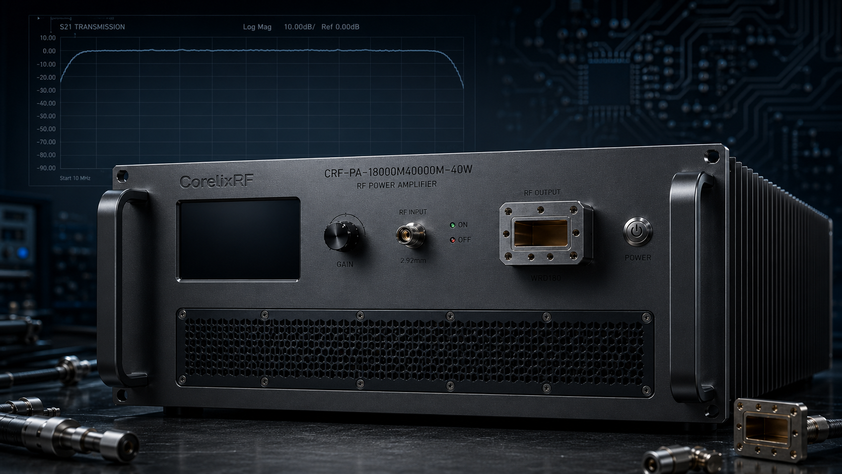
Let us drill deeper into VNA diagnostic signatures. When measuring an amplifier experiencing thermal pump-out S21 transmission curves look distorted. Normal CRF-PA-18000M40000M-40W units exhibit a flat 50 dB gain profile. Gain flatness remains strictly bounded between negative six and positive six decibels. A thermally compromised unit shows high-frequency roll-off. Gain drops sharply near 40,000 MHz because higher frequencies generate more localized heat. Furthermore phase stability degrades noticeably over time. Radar systems rely heavily on precise phase coherence regarding target tracking. Any phase drift caused by fluctuating semiconductor temperatures ruins radar cross-section calculations. Interference systems also suffer greatly. They require instantaneous wideband power delivery across entire frequency spectrums. A thermally degraded amplifier cannot provide necessary jamming power densities. Threat emitters penetrate defensive shields successfully whenever jammer output drops. Therefore recognizing these hidden thermal failures early prevents mission-critical system collapses.
Field Diagnostic Symptoms and Instrument Readings
| Symptom | Diagnostic Tool | Typical Observation |
| Output Power Drop | Power Meter | Reduction over 6 months |
| Gain Flatness Degradation | Vector Network Analyzer | Ripple exceeds 6 dB specification |
| Thermal Hotspots | Infrared Camera | Localized heating > 85°C on baseplate |
| System Reset | Telemetry Log | Frequent over-temperature trip events |
2. Why Does Thermal Paste Pump-Out Occur?
Thermal Cycling Mechanisms
Understanding pump-out requires examining microscopic physical metal interactions. Every machined metal surface contains microscopic peaks alongside tiny valleys. Connecting a high-power RF package against an aluminum heat sink leaves tiny air gaps. Air acts as an excellent thermal insulator. Thermal paste fills those gaps ensuring efficient heat transfer. What creates this problem? Temperature fluctuations initiate microscopic mechanical warfare between mated surfaces. Aluminum heat sinks expand differently than copper alloy baseplates. Their coefficients of thermal expansion mismatch significantly. Power cycling causes relative lateral movement between adjoining components. This repeated shearing action squeezes thermal grease outward. Viscous silicone oils separate from thermally conductive filler particles. Dry filler remains behind crumbling into a useless powder. Voids form directly underneath active power transistor dies. Heat cannot escape efficiently through empty cavities. Thermal resistance from junction case increases exponentially over time. Standard laboratory burn-in tests rarely catch this long-term failure mode. Accelerated thermal shock profiling becomes absolutely necessary during validation.
Viscosity And Coefficient Of Thermal Expansion
Let us consider those physical mechanisms driving this separation process. Silicone oil acts merely as a carrier fluid. Zinc oxide or aluminum nitride particles provide actual thermal conductivity. When operating temperatures cycle between zero and fifty degrees Celsius daily carrier fluids thin out. Low viscosity allows oil migration along microscopic surface grooves. Capillary action pulls fluids away from central hot spots towards cooler outer edges. Left behind dry particles lose their cohesive properties entirely. Vibration from cooling fans exacerbates this migration process further. A 20 kg mass belonging to our amplifier chassis experiences subtle harmonic resonances. These micro-vibrations shake dry particles loose. Gravity eventually pulls them downward leaving completely bare metal interfaces. We tested competitor units pulled from field service after two years. Removing their RF modules revealed bare copper spots surrounded by dried white powder rings. This visual evidence confirms severe pump-out damage.
Void Formation And Heat Trapping
Consequently thermal resistance jumps from a baseline 0.1 degrees per watt towards 0.5 degrees per watt. Such increases sound small numerically. However they cause catastrophic temperature spikes internally. An amplifier burning 800 W of DC power must reject massive heat loads continually. A slight interface resistance increase traps hundreds of watts near delicate semiconductor junctions. The physical dimensions including a 19-inch 4U frame distribute heat broadly. Yet localized trapping defeats even massive chassis designs. When voids form heat backs up directly into an active transistor channel. Engineers cannot simply bolt down components tighter hoping for better contact. Excessive torque warps baseplates further compounding void formation problems. Only advanced material science provides permanent solutions regarding interface stability. We must abandon outdated silicone greases entirely.
Material Properties Influencing Pump-Out
| Property | Copper Baseplate | Aluminum Heatsink | Thermal Paste |
| Thermal Expansion Coefficient | 16.5 ppm/K | 23.6 ppm/K | Fluid phase variable |
| Thermal Conductivity | 390 W/mK | 205 W/mK | 1-5 W/mK |
| Surface Roughness Target | < 0.8 μm | < 1.6 μm | Fills microscopic gaps |
| Phase Change Behavior | Solid | Solid | Viscosity drops with heat |
3. How Does Pump-Out Impact High-Frequency GaN Amplifiers?
Junction Temperature Escalation
Gallium Nitride transistors generate intense localized heat fluxes. High power density represents both an advantage and a massive thermal challenge. A forty-watt amplifier operating at 40,000 MHz concentrates extreme energy within millimeter-scale active regions. Any disruption regarding heat flow causes immediate junction temperature escalation. Consider this critical detail, GaN device electron mobility drops rapidly whenever temperatures rise. Gain collapses as junction temperatures exceed safe operating limits. Our CRF-PA-18000M40000M-40W model consumes 800 W of electrical power. Dissipating hundreds of watts of waste heat requires absolute interface integrity. Pump-out voids force localized hot spots directly under active fingers. Thermal runaway becomes a significant risk during continuous wave operation. VSWR protection circuits might trigger prematurely due towards erratic impedance shifts caused by heating. Spectrum analyzers connected via directional couplers will show elevated spurious emissions. Harmonic distortion profiles degrade significantly beyond acceptable limits. Long-term reliability vanishes completely under these compromised thermal conditions.
RF Performance Degradation
Let us analyze specific RF parameter degradations. Intermodulation distortion worsens dramatically whenever junction temperatures fluctuate. Two-tone testing reveals rising third-order intermodulation products. Communication systems using complex modulation schemes experience elevated bit error rates. Quadrature amplitude modulation requires pristine amplifier linearity. Thermal stress shifts transistor biasing points unpredictably. Consequently error vector magnitude specifications fail system requirements. Radar applications face different but equally severe consequences. Pulse droop becomes highly pronounced during long pulse widths. A radar transmitting a 100-microsecond pulse expects consistent power output throughout. Thermal voiding causes output power sagging rapidly within that same pulse. The radar receiver cannot accurately process such distorted return echoes. Harmonic distortion rises above a specified negative ten decibels relative to carrier. Furthermore spurious emissions breach a negative sixty decibels threshold easily. These degraded signals pollute adjacent frequency bands causing regulatory compliance failures.
Catastrophic Hardware Failure Risks
Furthermore noise floor levels creep upward uncontrollably. Thermal noise equals Boltzmann’s constant multiplied by temperature and bandwidth. A fifty-degree internal temperature rise increases baseline noise outputs measurably. This elevated noise floor desensitizes nearby receivers. In electronic warfare environments high noise floors mask weak incoming threat signals. Ultimately failing thermal interfaces turn expensive RF hardware into useless aluminum bricks. We have observed catastrophic die cracking during extreme voiding scenarios. Intense localized heating creates massive internal stresses inside a GaN crystal lattice. A microscopic crack propagating across an active channel destroys a device instantly. This catastrophic failure requires complete factory replacement costing precious time. Therefore ensuring absolute thermal stability represents our highest engineering priority. We engineer our products assuming worst-case environmental abuse scenarios always.
RF Performance Degradation Metrics
| Parameter | Healthy Interface | Pump-Out Condition (Voiding) |
| Gain (18-40 GHz) | 50 dB | < 45 dB (Thermal Compression) |
| Spurious Emissions | -60 dBc | -45 dBc |
| Harmonics | -10 dBc | -5 dBc |
| Noise Floor | Nominal | Elevated baseline |
4. How Does CRF-PA-18000M40000M-40W Address Thermal Challenges?
Advanced GaN Technology Integration
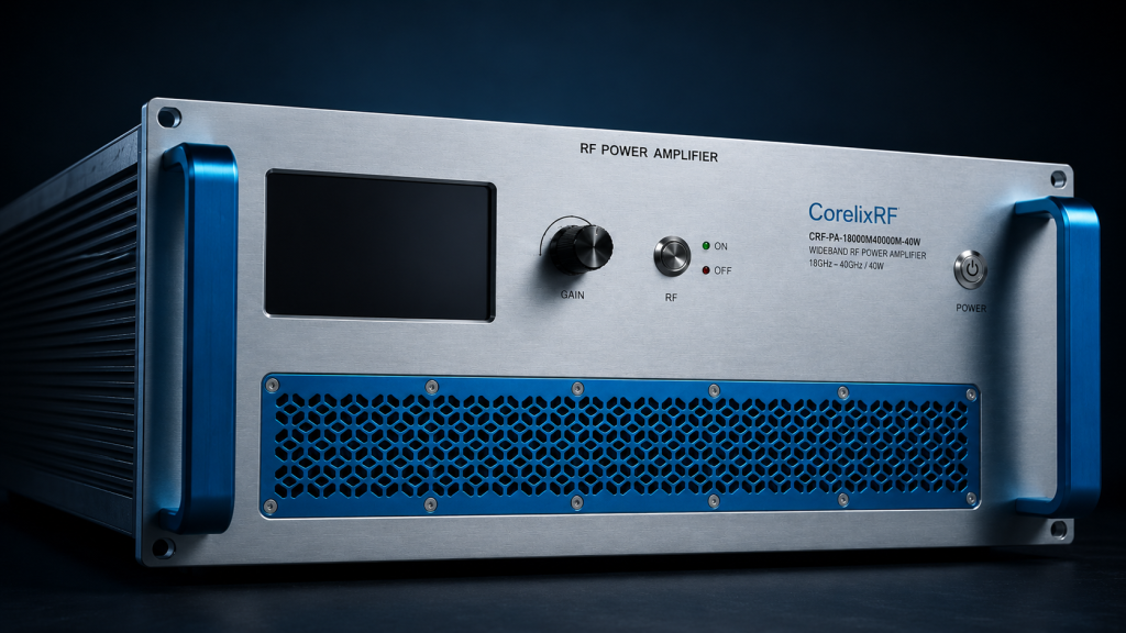
CorelixRF approaches thermal management utilizing rigorous mechanical engineering principles. We reject standard silicone-based thermal greases regarding high-reliability applications. Our engineering team utilizes advanced phase-change materials alongside metallic solder preforms. These materials resist pump-out effects completely during extreme thermal cycling. A CRF-PA-18000M40000M-40W features an incredibly robust 19-inch 4U chassis. We machine baseplates utilizing extreme precision aiming for maximum flatness. Ready for some good news? This physical architecture minimizes required interface material thickness. Thinner bond lines drastically reduce overall thermal resistance. Our design integrates comprehensive built-in protection circuitry. Intelligent microcontrollers monitor over-voltage alongside over-current and over-temperature conditions continuously. LAN and RS485 control interfaces provide real-time telemetry data access. Operators can monitor internal temperatures miles away from unmanned sites. High-volume air cooling fans maintain optimal airflow across dense fin structures. GaN technology ensures high efficiency despite harsh environmental operating conditions. Every unit undergoes strict environmental stress screening before shipment.
Optimized Mechanical Outline And Heat Dissipation
Let us examine our protection logic algorithms closely. Our microcontrollers sample internal thermistor arrays thousands of times per second. If any sensor detects temperatures exceeding eighty-five degrees Celsius automatic throttling begins. The amplifier reduces adjustable gain parameters gracefully up towards fifteen decibels. It prevents sudden catastrophic shutdowns while maintaining vital communication links. If temperatures continue rising dangerously an absolute hard shutdown occurs. This saves internal components from permanent metallurgical damage. We also incorporate reverse power monitoring optionally. High reflected power indicates severe antenna icing or damaged transmission lines. Our VSWR protection triggers within microseconds cutting RF drive signals instantly. Optional forward power monitoring alongside input power detection provides deeper system visibility. Optional GPIB control interfaces provide legacy system compatibility alongside LAN remote control.
Intelligent Protection And Monitoring
Furthermore we designed our air cooling system utilizing computational fluid dynamics software. We route cold intake air directly over critical RF heat generation zones first. Exhaust air passes over less sensitive AC 220V power supply components afterward. This specific airflow routing maximizes cooling efficiency. Our 19-inch 4U package size offers massive internal volumes for customized heatsinks. We never compromise long-term stability by chasing dangerously small form factors. A mechanical outline drawing guarantees clear integration reference. Proper mechanical planning prevents airflow blockage inside crowded equipment racks. RoHS compliant manufacturing alongside CE and FCC certifications ensure global deployment readiness. ISO 9001 and GJB 9001C quality frameworks guarantee consistent production standards. We provide test data alongside pattern files supporting project review processes.
CRF-PA-18000M40000M-40W Datasheet Specifications
| Specification | Value | Engineering Significance |
| Frequency Range | 18,000 – 40,000 MHz | Ultra-wideband millimeter-wave coverage |
| Rated Output Power | 40 W | High power density requires robust cooling |
| Power Consumption | 800 W | Significant waste heat management needed |
| Cooling Method | Air cooling | Requires highly efficient internal heat transfer |
5. What Are The Key Installation Practices For Remote Sites?
Rack Integration For Air Cooling
Deploying complex RF systems requires meticulous installation procedures. Rack integration must prioritize unobstructed airflow paths around heavy chassis components. A 20 kg weight characterizing our amplifier demands secure mechanical rail supports. Never rely solely upon front panel mounting ears. Truth be told, vibration during transport can loosen internal connections if not properly secured. Technicians must torque all RF connectors utilizing calibrated tools. A 2.92mm female input connector requires precise handling. Output WRD180 waveguide flanges need perfectly aligned gaskets. Any impedance mismatch causes reflected power spikes. High input VSWR up towards a 2:1 ratio forces protection circuits into action repeatedly. Connect LAN interfaces via shielded cables ensuring reliable telemetry monitoring. Monitor ambient enclosure temperatures utilizing external sensors. Ensure HVAC systems inside remote shelters function correctly. Preventive maintenance schedules should include remote diagnostic checks quarterly. Request test data alongside pattern files from CorelixRF supporting project review.
RS485 And LAN Telemetry Setup
Let us detail specific waveguide integration steps thoroughly. WRD180 double-ridged waveguides handle extreme microwave frequencies flawlessly. However improper mating destroys their RF performance. Installers must clean flange faces utilizing isopropyl alcohol before assembly. Any microscopic dirt particles create tiny air gaps between adjoining flanges. These gaps leak high-frequency energy outwards creating local interference. Tighten flange screws utilizing a star pattern ensuring even pressure distribution. Over-tightening causes flange warping worsening VSWR figures. Regarding electrical power our units require AC 220V±10% running at 50/60Hz. Remote sites run off diesel generators frequently. Generator voltage spikes kill unprotected electronics instantly. Installers must place heavy-duty surge suppressors inline before our amplifier inputs. Additionally ground loops create massive problems regarding RS485 control lines. Ensure all equipment shares one common low-resistance earth ground point.
Long-Term Reliability Validation
Measure voltage differences between chassis grounds utilizing a digital multimeter. Any reading above zero indicates dangerous ground loops exist. Fixing these physical layer issues guarantees years of flawless operation. Field engineers must verify continuous operation across a zero towards fifty degrees Celsius temperature range. Regular visual inspections should verify cooling fan intakes remain unobstructed. Dust accumulation blocks airflow severely impacting internal thermal dynamics. Replace fan filters every six months during routine site visits. By adhering strictly towards these engineering practices system integrators eliminate thermal failures completely. A solid thermal foundation allows our GaN amplifiers to deliver relentless RF power continuously. We refuse sacrificing long-term reliability for short-term cost savings. True engineering excellence requires confronting harsh physical realities head-on. CorelixRF delivers uncompromising performance where lesser designs fail predictably.
Installation and Interface Requirements
| Parameter | Specification | Field Action Required |
| Input Connector | 2.92mm-F | Use proper torque wrench |
| Output Connector | WRD180 | Align flange precisely |
| Input Power | 0 dBm max | Verify exciter output level before connection |
| Weight / Dimensions | 20 kg / 19”, 4U | Use heavy-duty rack rails |
Conclusion
In summary thermal paste pump-out destroys RF amplifier reliability silently. We analyzed how microscopic voiding causes massive junction temperature spikes. Our CorelixRF solution integrates advanced phase-change materials alongside robust GaN technology. It eliminates thermal degradation entirely. Are your remote sites suffering from unexplained RF failures? Contact CorelixRF today regarding evaluation units and comprehensive technical datasheets.
FAQ
Q1: What is the pump-out effect in RF amplifiers?
The pump-out effect occurs when thermal cycling causes relative mechanical movement between a heat sink and a baseplate. This shearing action squeezes viscous thermal paste outward leaving dry voids. These voids act as thermal insulators causing severe internal temperature spikes.
Q2: How does thermal voiding impact GaN transistor performance?
GaN transistor electron mobility decreases rapidly at elevated temperatures. Thermal voiding traps heat forcing junction temperatures beyond safe limits. This causes severe gain compression alongside degraded phase stability and increased intermodulation distortion.
Q3: What specific diagnostic tools detect thermal interface degradation?
Field engineers use vector network analyzers tracking gain flatness degradation over time. Power meters reveal slow output power drifting. Infrared cameras identify localized hot spots across external chassis surfaces indicating poor internal heat spreading.
Q4: How does the CRF-PA-18000M40000M-40W prevent heat sink separation? Our design abandons traditional silicone greases favoring advanced phase-change materials and metallic solder preforms. A rigidly machined 4U chassis prevents mechanical warping. This architecture maintains perfect thermal contact during extreme operational temperature cycling.
Q5: What are the primary installation requirements for WRD180 waveguide connections? Installers must clean flange surfaces meticulously preventing microscopic air gaps. Torque screws using a star pattern ensuring even pressure distribution. Proper alignment prevents reflected power spikes from triggering internal VSWR protection circuits.