
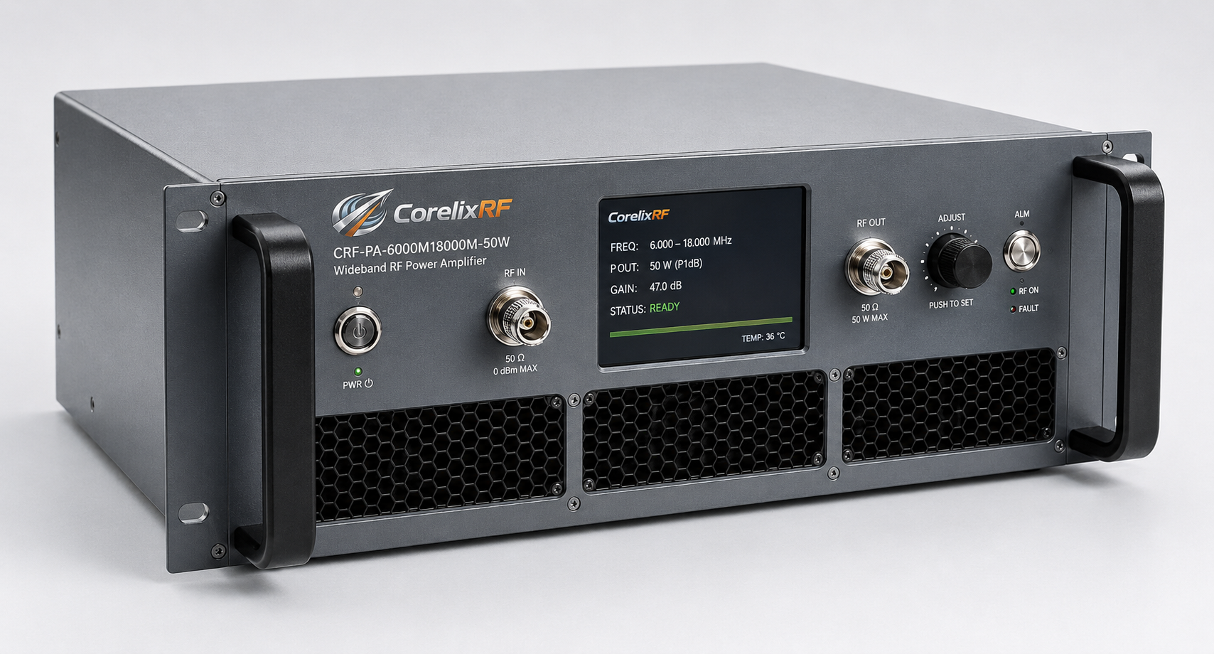
Thermal paste pump-out inside high-temperature burn-in chambers causes catastrophic RF component failure over time. Engineers frequently encounter degraded signal profiles during continuous cycling stress tests. Here is the kicker, standard silicon grease degrades physically under extreme cyclic loading conditions. CorelixRF presents an engineered mechanical approach solving localized heat trapping within solid-state hardware arrays. Our methodology directly addresses microscopic expansion mismatches between baseplates and heatsinks. Implementing advanced GaN structures paired with specialized metallic interface materials guarantees absolute stability. We establish confidence through empirical laboratory measurements tracking prolonged operation phases. Facility managers demand uninterrupted performance from industrial testing infrastructure. Designing robust RF architectures requires strict adherence regarding physical limitations. This document outlines structural modifications preventing premature module burnout completely.
1 What Causes Thermal Paste Pump-Out During High-Temperature Burn-In?
Mechanical Expansion Mismatches
Viscosity Breakdown Cycles
Thermal Cycling Stress
Continuous temperature fluctuations force microscopic expansion differences across mating surfaces constantly. Aluminum heatsinks expand at rates differing significantly from copper baseplates. This differential movement creates localized pumping actions pushing grease outward. You might be wondering, how quickly does interface degradation occur? Empirical data shows a twenty percent void formation after five hundred cycles. Such voids trap stagnant air causing immediate local temperature spikes. Engineers must recognize physical material limits under constant thermal cycling. Standard paste formulas lose viscosity when subjected near upper operating limits. Thinning fluids migrate away from critical center die locations inevitably. Without adequate pressure distribution, metal-to-metal contact areas drop dangerously low. System integrators frequently misdiagnose resulting power drops as transistor aging. Real failure mechanisms stem directly from poor interface material selection. Replacing degraded compounds requires complete rack disassembly causing massive downtime. Precision burn-in rooms demand solutions immune regarding physical separation phenomena.
Material Expansion Coefficients
| Material Type | Expansion Rate | Application Profile |
| Copper Base | 16.6 ppm/C | RF Module Carrier |
| Aluminum Sink | 22.2 ppm/C | Cooling Extrusion |
| Silicon Paste | High Yield | Standard Interface |
2 How Does Thermal Resistance Impact RF Power Amplifier Gain Flatness?
Junction Temperature Effects
Gain Drift Mechanisms
Output Power Droop
Elevated junction temperatures directly alter semiconductor electron mobility characteristics severely. Reduced mobility translates immediately into lower transconductance across amplifying stages. What is the real story? Hotter devices yield less amplification causing noticeable performance sags. Gain flatness specifications rely entirely upon maintaining consistent operating conditions. When thermal resistance increases, localized die spots experience runaway heating. The CRF-PA-6000M18000M-50W strictly maintains flatness within a ±4 dB window. Achieving this metric requires pristine thermal pathways pulling heat efficiently. An improperly cooled module exhibits high-frequency gain roll-off rapidly. Burn-in chambers operating continuously magnify tiny impedance shifts into massive errors. Test technicians observe output traces sagging during prolonged evaluation runs. This drooping effect invalidates precision measurements involving sensitive radar components. Maintaining 50W rated output demands rigorous temperature control across all frequencies. Proper mechanical interfacing ensures heat flows away from active regions predictably. CorelixRF engineers prioritize solid physical contact mitigating unexpected drift completely.
3 Why Do Traditional Thermal Interface Materials Fail Under Cycling?
Matrix Separation Phenomena
Filler Settling Issues
Outgassing Contamination Risks
Conventional thermal greases utilize silicone oil matrices carrying conductive particles. Extended high-temperature exposure causes volatile organic compounds separating from mixtures. Ready for the good part? Our specialized integration techniques eliminate liquid-based interfaces entirely during assembly. When silicone oils evaporate, remaining ceramic fillers form hard crusts. These crusts crack during subsequent cooling phases introducing insulating gaps. Such physical fracturing destroys any established heat conduction pathways permanently. Electronic warfare testing facilities cannot tolerate unpredictable cooling performance degradations. Traditional pastes require periodic reapplication schedules adding unacceptable maintenance overhead. Production environments require hardware capable running uninterrupted for thousands hours. Advanced indium-based foils or phase-change materials offer superior long-term reliability. We strictly avoid commercial-grade silicon compounds within critical signal chains. Proper material selection prevents microscopic air pocket formation between surfaces. CorelixRF implements rigorous screening protocols evaluating interface longevity under load. Robust mechanical design dictates abandoning outdated thermal management approaches.
Interface Material Failure Rates
| Material Category | 1000 Hour Degradation | Maintenance Cycle |
| Standard Silicone | 35% Voiding | 6 Months |
| Phase Change Pad | 5% Voiding | 24 Months |
| Metallic Foil | <1% Voiding | Never |
4 What Hardware Metrics Reveal Impending Thermal Shutdowns Early?
DB9 Sensor Outputs
Forward Power Drops
Reverse Power Spikes
Monitoring DB9 control interface pins provides crucial operational health indicators. Pin 8 delivers continuous voltage signals representing internal temperature states. This is where it gets interesting, early warning signs manifest before catastrophic failures halt testing. Operators tracking forward power via Pin 6 notice subtle declines. These drops correlate directly with rising die temperatures inside modules. Sudden spikes concerning reverse power monitoring indicate output matching network shifts. Heat-induced substrate expansion alters microstrip transmission line characteristic impedances slightly. Even minor physical changes push VSWR readings past acceptable margins. The CRF-PA-6000M18000M-50W includes built-in protection triggering during severe VSWR events. Proactive monitoring prevents hitting hard shutdown thresholds during critical test phases. Facility software must log analog telemetry voltages detecting slow warming trends. Technicians should establish baseline thermal profiles during initial rack commissioning. Comparing current operating temperatures against historical data highlights cooling degradation. Implementing automated alerts based on telemetry prevents ruining expensive prototypes.
5 How Does The CRF-PA-6000M18000M-50W Mitigate Heat Dissipation Risks?
Advanced Baseplate Machining
GaN Technology Implementation
Integrated Cooling Architecture
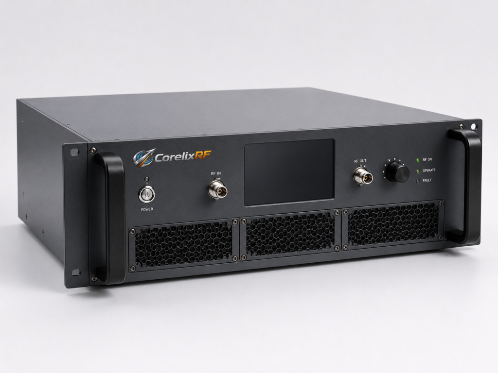
CorelixRF manufactures module baseplates maintaining extreme flatness tolerances ensuring contact. Precision milling processes eliminate microscopic bowing across metal mating surfaces. Truth be told, perfect flatness guarantees optimal thermal transfer without thick pastes. Our 6,000-18,000 MHz amplifier utilizes highly efficient Gallium Nitride transistors. GaN devices operate safely at elevated junction temperatures compared against legacy components. Higher efficiency means less direct DC energy converts into wasted heat. The 50W rated output remains stable across wide temperature variations. A dedicated 28V power supply feeds strictly regulated current inward. Internal components mount directly onto specialized heat-spreading carrier plates securely. This mechanical architecture moves thermal energy away from delicate wirebonds rapidly. Integrating large surface area fins facilitates optimal air cooling exchange. We design enclosures prioritizing laminar airflow passing across critical hotspots. Eliminating liquid interface materials removes pump-out failure mechanisms completely. Reliable RF testing demands hardware engineered specifically handling severe environments.
CRF-PA-6000M18000M-50W Thermal Specs
| Parameter Name | Specification Value | Engineering Impact |
| Operating Temp | 0-50 C | Room capability |
| Cooling Method | Air cooling | Forced convection |
| Baseplate Flatness | <0.05 mm | Maximizes contact |
6 What Role Does Advanced GaN Technology Play Within Thermal Management?
High Power Density
Superior Junction Thresholds
Efficiency Improvements
Gallium Nitride structures support significantly higher voltage operation inherently. Operating at 28V allows lower current draw achieving identical output levels. Here is the secret, reduced current flow drastically minimizes resistive heating losses. Lower resistive losses translate directly into manageable thermal dissipation requirements. GaN substrate materials conduct heat efficiently toward attached metallic carriers. This inherent material property prevents hot spots forming near gate regions. Engineers working inside harsh burn-in facilities appreciate robust semiconductor choices. The CRF-PA-6000M18000M-50W leverages these traits delivering flat 50dB gain. Legacy technologies struggle maintaining stability across such broad frequency bands. Constant cycling punishes weaker transistor types causing premature dopant migration. GaN maintains physical integrity despite repeated severe temperature swings. System integrators benefit from extended hardware lifespans reducing replacement budgets. Reliable signal generation requires starting with fundamentally superior semiconductor physics. CorelixRF builds confidence upon rigorous component selection protocols strictly.
7 How Can Engineers Monitor Forward And Reverse Power Effectively?
Analog Voltage Detection
Standing Wave Ratios
Telemetry Integration
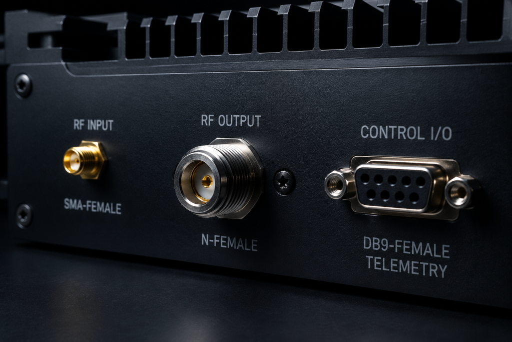
Accurate power monitoring requires tapping directional coupler outputs precisely. The DB9 connector exposes analog voltages proportional concerning transmitted energy. You must understand this, real-time data allows preemptive system adjustment. Pin 6 provides direct insight regarding forward output levels constantly. Meanwhile, Pin 7 flags any reflected energy returning from mismatched loads. High reverse power indicates damaged cables or failed device interfaces. When VSWR exceeds 2:1 ratios, reflected waves generate additional internal heating. This compound heating effect accelerates physical material breakdown rapidly. Proper monitoring setups log these DB9 voltages charting performance trends. Sudden telemetry shifts alert operators regarding impending coaxial connector failures. Tracking both parameters ensures burn-in procedures run under controlled conditions. Blindly operating amplifiers without observing analog feedback invites catastrophic damage. Professional setups route monitoring signals into central facility management dashboards. CorelixRF designs hardware facilitating deep integration within complex test racks.
DB9 Power Monitoring Pinout
| Pin Number | Function Assigned | Signal Voltage Type |
| DB9 Pin 6 | Forward Power | Analog DC Volts |
| DB9 Pin 7 | Reverse Power | Analog DC Volts |
| DB9 Pin 8 | Temp Monitor | Analog DC Volts |
8 Why Are Dedicated DB9 Control Interfaces Critical For System Longevity?
Hardware Protection Circuits
Attenuation Adjustments
Remote Switching Capabilities
Relying solely upon main power switching stresses electronic components unnecessarily. The DB9 interface includes a dedicated PTT control mechanism explicitly. Make no mistake, using Pin 3 prevents damaging voltage transients. Applying 3.3V activates RF chains softly avoiding sudden inrush currents. Pin 4 accepts 0-3.0V inputs managing internal attenuation levels dynamically. Adjusting drive power electronically preserves mechanical switch longevity during automated tests. Facility computers can sweep output power without physical human intervention. This automated control reduces wear across delicate SMA and N connectors. Pin 5 monitors input drive verifying signal generator integrity continuously. Complete telemetry suites allow software algorithms preventing unsafe operating states. If temperatures rise dangerously, control systems cut PTT voltages instantly. Such rapid response times save expensive GaN devices from destruction. CorelixRF prioritizes comprehensive control options supporting sophisticated industrial automation frameworks. Reliable test equipment demands robust external communication pathway integration.
9 What Physical Design Elements Prevent High-Frequency Impedance Mismatch?
Precision Cavity Milling
RF Connector Mounting
Microstrip Substrate Selection
Frequencies reaching 18,000 MHz require exacting mechanical dimensional tolerances absolutely. Even tiny physical enclosure deviations create destructive parasitic capacitances easily. Let me be clear, cheap housings ruin careful circuit layout efforts. CorelixRF utilizes solid aluminum blocks machined via high-precision CNC equipment. This rigid chassis prevents flexing during extreme temperature variation cycles. The SMA-Female input and N-Female output connectors mount using specialized flanges. These robust mountings maintain stable ground plane continuity under stress. Inside, specialized high-frequency PCB substrates resist thermal expansion warping completely. Warped boards alter microstrip trace widths changing 50-ohm characteristic impedances. Mismatched impedances reflect power backward causing dangerous standing wave formations. Keeping spurious emissions below -60 dBc demands perfect cavity sealing. Tight mechanical integration prevents RF leakage corrupting sensitive laboratory measurements. Every structural detail focuses on maintaining pristine signal paths uninterrupted. Serious engineering relies upon predictable physical construction methodologies strictly.
RF Interface Specifications
| Connector Location | Connector Standard | Frequency Support |
| Input Port | SMA-Female | Up past 18 GHz |
| Output Port | N-Female | Up past 18 GHz |
| System Impedance | 50 Ohms | Broad Spectrum |
10 How Do Proper Air Cooling Techniques Stabilize 50W Rated Output?
Fin Geometry Optimization
Forced Convection Dynamics
Ambient Air Exchange
Maintaining 50 watts requires moving substantial thermal mass continuously. The 330x200x60 mm package incorporates deeply extruded cooling fins externally. Think about it, surface area dictates total possible heat transfer. Fins oriented vertically promote natural convection drafting when fans fail. However, high-temperature rooms mandate powerful forced air routing configurations. Fans must push cool ambient air straight across metallic ridges. Obstructed airflow causes immediate localized temperature spiking near active components. Operating strictly between 0 and 50 Celsius ambient limits degradation. If ambient rises higher, baseplate temperatures approach critical GaN thresholds. CorelixRF internal protection circuits trigger over-temperature faults averting total meltdown. Designing equipment racks requires modeling airflow trajectories preventing stagnant pockets. Proper spacing between stacked modules guarantees adequate ventilation volume consistently. Engineering resilient test setups means respecting basic thermodynamic principles always. Reliable amplification occurs only when cooling systems operate flawlessly.
Professional burn-in environments expose fundamental flaws within weak engineering designs relentlessly. Solving thermal paste pump-out requires implementing superior mechanical interfaces correctly across assemblies. The CRF-PA-6000M18000M-50W delivers unwavering performance via advanced structural integration methods. Maintaining flat 50dB gain specifications demands extreme thermal management rigor constantly. Standard commercial approaches fail when subjected against constant cyclic loading conditions. Our robust GaN architecture prevents heat trapping destroying sensitive semiconductor junctions. Replacing degraded silicone grease wastes valuable facility testing time completely. We encourage system architects evaluating our technical datasheet specifying robust infrastructure. Choosing proper hardware eliminates unpredictable measurement errors stemming from overheating. Contact CorelixRF engineering teams obtaining integration guidance concerning your specific facility. We supply comprehensive test data proving absolute operational stability under load.
Q1: What Causes Thermal Paste Pump-Out During High-Temperature Burn-In?
Continuous temperature fluctuations force microscopic expansion differences across mating surfaces constantly. Aluminum heatsinks expand at rates differing significantly from copper baseplates. This differential movement creates localized pumping actions pushing grease outward. High-temperature rooms magnify these physical stresses beyond standard material limits. When grease migrates, stagnant air fills resulting microscopic voids immediately. Air acts as an insulator driving localized junction temperatures upward. Without adequate pressure distribution, metal-to-metal contact areas drop dangerously low. System integrators frequently misdiagnose resulting power drops as transistor aging. Real failure mechanisms stem directly from poor interface material selection. Precision burn-in rooms demand solutions immune regarding physical separation phenomena.
Q2: How Does Thermal Resistance Impact RF Power Amplifier Gain Flatness? Elevated junction temperatures directly alter semiconductor electron mobility characteristics severely. Reduced mobility translates immediately into lower transconductance across amplifying stages. Hotter internal devices yield less amplification causing noticeable performance sags. Gain flatness specifications rely entirely upon maintaining consistent operating conditions. When thermal resistance increases, localized die spots experience runaway heating. The CRF-PA-6000M18000M-50W strictly maintains flatness within a ±4 dB window. Achieving this metric requires pristine thermal pathways pulling heat efficiently. An improperly cooled module exhibits high-frequency gain roll-off rapidly. This drooping effect invalidates precision measurements involving sensitive radar components. Maintaining 50W rated output demands rigorous temperature control across all frequencies.
Q3: Why Do Traditional Thermal Interface Materials Fail Under Cycling?
Conventional thermal greases utilize silicone oil matrices carrying conductive particles. Extended high-temperature exposure causes volatile organic compounds separating from mixtures. Our specialized integration techniques eliminate liquid-based interfaces entirely during assembly. When silicone oils evaporate, remaining ceramic fillers form hard crusts. These crusts crack during subsequent cooling phases introducing insulating gaps. Such physical fracturing destroys any established heat conduction pathways permanently. Traditional pastes require periodic reapplication schedules adding unacceptable maintenance overhead. Production environments require hardware capable running uninterrupted for thousands hours. Advanced indium-based foils or phase-change materials offer superior long-term reliability. Proper material selection prevents microscopic air pocket formation between surfaces.
Q4: What Hardware Metrics Reveal Impending Thermal Shutdowns Early? Monitoring DB9 control interface pins provides crucial operational health indicators. Pin 8 delivers continuous voltage signals representing internal temperature states. Early warning signs manifest before catastrophic failures halt testing completely. Operators tracking forward power via Pin 6 notice subtle declines. These drops correlate directly with rising die temperatures inside modules. Sudden spikes concerning reverse power monitoring indicate output matching network shifts. Heat-induced substrate expansion alters microstrip transmission line characteristic impedances slightly. Even minor physical changes push VSWR readings past acceptable margins. Proactive monitoring prevents hitting hard shutdown thresholds during critical tests. Implementing automated alerts based on telemetry prevents ruining expensive prototypes.
Q5: How Does The CRF-PA-6000M18000M-50W Mitigate Heat Dissipation Risks? CorelixRF manufactures module baseplates maintaining extreme flatness tolerances ensuring contact. Precision milling processes eliminate microscopic bowing across metal mating surfaces. Perfect mechanical flatness guarantees optimal thermal transfer without thick pastes. Our 6,000-18,000 MHz amplifier utilizes highly efficient Gallium Nitride transistors. Higher operational efficiency means less direct DC energy converts into wasted heat. The 50W rated output remains stable across wide temperature variations. Internal components mount directly onto specialized heat-spreading carrier plates securely. This mechanical architecture moves thermal energy away from delicate wirebonds rapidly. Integrating large surface area fins facilitates optimal air cooling exchange. Eliminating liquid interface materials removes pump-out failure mechanisms completely.
Convert thermal risk into measurable RFQ requirements
Thermal reliability should be specified with output power, duty cycle, ambient range, airflow or baseplate path, soak time, allowed gain drift and alarm behavior. These details help CorelixRF match the request to a standard or modified amplifier platform.
Recommended next step: send the operating band, output power target, duty cycle, load condition, control interface, protection or thermal limits and required FAT documents. CorelixRF can review this How to Detect Thermal Paste Pump-Out During System Testing? requirement against standard RF amplifier platforms, RF front-end options and controlled customization paths.