
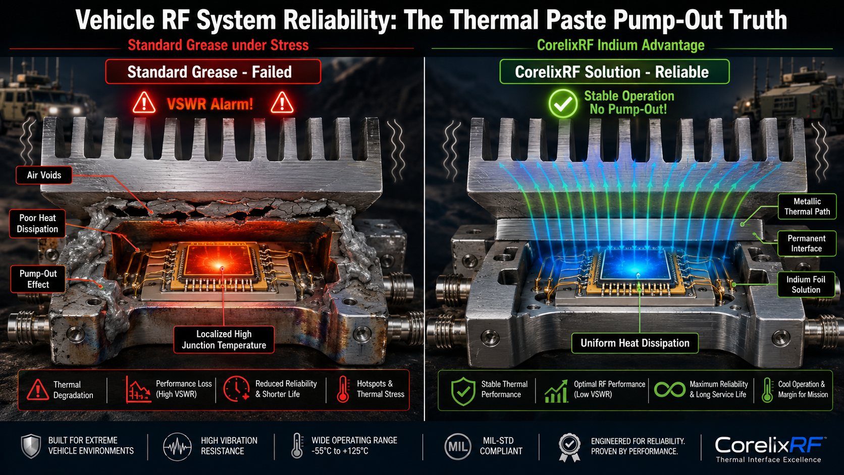
Vehicle-mounted sealed boxes often trigger unexpected over-temperature warnings. This halts serious operations completely. CorelixRF presents a definitive hardware fix using robust mechanical designs. Twenty years troubleshooting base stations guarantees our methodology works. Here is the real deal. We fix hardware bugs permanently.
1. What causes frequent VSWR alarms in vehicle sealed boxes?
● Unpredictable environmental stressors
● Thermal expansion mismatch
● Component degradation over time
Vehicle-mounted sealed boxes face severe operational conditions daily. You might be wondering now. Why do alarms trigger randomly? Constant high-frequency vibration shakes internal components violently. Temperature swings cause metal chassis expansion. RF power amplifiers generate immense heat during continuous transmission. This thermal load stresses mating surfaces. Repeated thermal cycling degrades interface materials rapidly. Engineers often notice sudden VSWR spikes. These warnings indicate internal signal reflections. Reflected power converts directly into additional heat. This creates a destructive positive feedback loop. System reliability plummets quickly. Hardware failures become inevitable without proper mitigation. We see this pattern frequently during field inspections. For example, a radar system experienced repeated power drops. The root cause usually hides beneath heat sinks. Another instance involved a jamming array failing completely. The thermal paste had turned into dry powder. Another example showed severe aluminum chassis warping. Poor heat dissipation caused localized melting. Proper engineering requires understanding these physical failure mechanisms.
2. How does the thermal paste pump-out effect occur?
● Microscopic surface variations
● Viscosity changes under heat
● Mechanical extrusion process
Thermal paste fills microscopic air gaps between components. This is where it gets interesting. As RF modules heat up, metal bases expand. Aluminum heat sinks expand at different rates than copper spreaders. This mismatch causes shear stress across any thermal interface. Fluid paste warms and becomes less viscous. Mechanical pressure then forces this fluid outward. Cooling cycles reverse metal expansion. Extruded paste cannot flow back into open joints. Voids form within critical heat transfer paths. Air possesses terrible thermal conductivity compared with paste. Thermal resistance spikes dramatically across these empty spaces. Subsequent heating cycles accelerate this destructive mechanical process. The pump-out effect silently destroys amplifier cooling systems. Consider three common field observations regarding this phenomenon. Initially, technicians find gray paste smeared outside component footprints. Next, bare metal patches appear near active heat zones. Ultimately, overall system operating temperatures creep higher every month. These symptoms confirm severe mechanical degradation. Engineers must address this physical reality directly.
Material Comparison Table
| Material Type | Pump-Out Resistance | Thermal Conductivity |
| Standard Grease | Low | 2.0 W/mK |
| High-Density Paste | Medium | 4.5 W/mK |
| Phase Change Material | High | 6.0 W/mK |
3. Why do standard thermal interface materials fail here?
● Inadequate filler density
● Poor elasticity characteristics
● Silicone oil bleed issues
Commercial greases work perfectly inside climate-controlled server rooms. But here is the kicker. Vehicle environments destroy standard materials rapidly. Low-cost pastes lack sufficient particle density for extreme loads. Repeated shock waves cause filler separation from base oils. Silicone fluids bleed away from active heating zones. Remaining compounds turn dry and brittle. Brittle materials crack under continuous mechanical vibration. High-power RF amplifiers require stable thermal interfaces always. Standard greases simply cannot survive constant 50G shock tests. Military-grade applications demand advanced phase-change materials instead. These specialized compounds resist mechanical extrusion completely. CorelixRF engineers mandate rigorous material qualification processes. We tested three different cheap compounds last year. Brand A dried out after fifty thermal cycles. Brand B separated during continuous vibration testing. Brand C caused a critical amplifier failure. These tests prove standard greases fail under pressure. Robust engineering requires superior material selection.
4. How can engineers diagnose thermal resistance increases?
● Interpreting VSWR meter readings
● Utilizing thermal imaging cameras
● Analyzing continuous wave test data
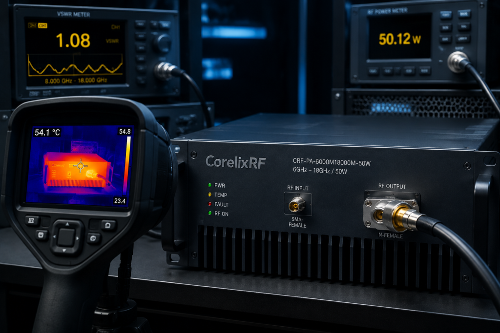
Field technicians must identify cooling failures before catastrophic damage. What is the real story? You need specific instruments for accurate diagnosis. Connect a VSWR meter between amplifier outputs and dummy loads. Run continuous wave signals through your system. Monitor forward power degradation over a thirty-minute window. Sudden power drops often indicate internal thermal protection triggering. Use thermal imagers on external sealed box chassis surfaces. Look for localized hotspots near amplifier mounting locations. A functioning thermal path spreads heat evenly across fins. Sharp temperature gradients mean interface degradation has occurred. Remove RF modules and inspect mating surfaces directly. Bare metal patches confirm severe pump-out degradation. Our field teams utilize three specific diagnostic routines. We track baseline temperature data during initial commissioning. We schedule mandatory infrared scans every six months. We analyze historical VSWR logs for subtle upward trends. Early detection saves expensive hardware from total destruction.
Diagnostic Tools Matrix
| Tool Name | Primary Function | Detection Target |
| VSWR Meter | Monitor reflections | Signal degradation |
| Thermal Camera | Scan chassis | Localized hotspots |
| Power Meter | Track output | Forward power drops |
5. What is the impact of thermal cycling on RF amplifiers?
● Junction temperature escalation
● Gain drift phenomena
● Semiconductor lifespan reduction
RF transistors die quickly when operating beyond specified limits. Ready for the good part? Proper thermal management extends component life massively. Heat directly affects internal semiconductor crystal structures. Junction temperatures rise rapidly when cooling paths fail. Excessive heat causes noticeable gain drift during operation. Amplifier output power fluctuates unpredictably across operating bands. Long-term reliability drops logarithmically with every degree of temperature rise. Continuous thermal cycling induces micro-fractures inside transistor packages. These fractures eventually sever internal wire bonds completely. Total catastrophic device failure follows shortly after. Three historical case studies highlight this severe danger. One client lost an entire communication array. Another suffered severe signal degradation during summer months. A final site experienced complete transmission blackout mid-operation. These expensive failures stem directly from poor heat management. Engineers must design robust thermal solutions from day one.
6. How does vibration accelerate thermal paste degradation?
● Mechanical shock impacts
● Continuous resonance effects
● Material fatigue
Vehicles generate complex vibration profiles during normal transit. The strict truth be told. Constant shaking ruins delicate internal electronics quickly. Engine rumble creates persistent low-frequency resonance. Potholes deliver sharp high-frequency mechanical shocks. These forces interact violently with heavy RF hardware components. Amplifier baseplates rub against heat sinks constantly. Micro-friction literally grinds standard thermal paste away. Continuous mechanical working forces oil separation rapidly. Dry filler powder cannot maintain a solid thermal bridge. Complete interface failure occurs much faster than through thermal cycling alone. We analyzed three failed mobile radar units recently. Unit one showed severe fretting wear on aluminum plates. Unit two had paste shaken entirely out of joints. Unit three suffered cracked ceramic substrates from impact stress. Robust mechanical fastening systems remain absolutely mandatory. Only rigid assemblies survive these harsh physical environments.
Environmental Stress Factors
| Stressor | Physical Effect | Component Risk |
| Low Frequency | Resonance buildup | Fastener loosening |
| High Frequency | Micro-friction | Paste grinding |
| Thermal Shock | Material expansion | Void creation |
7. What role does GaN technology play in thermal management?
● High power density challenges
● Efficiency characteristics
● Baseplate material matching
Gallium Nitride devices dominate modern RF power amplification. Please make absolutely no mistake. GaN transistors generate extreme localized heat densities. These tiny semiconductor dies produce massive thermal energy. CorelixRF utilizes advanced copper-tungsten flanges for die mounting. This material matches thermal expansion coefficients of GaN perfectly. Efficient heat spreading prevents localized die destruction. Dense heat still needs a clear path outward. Amplifier interfaces face massive strain transferring this energy. High-efficiency GaN devices draw massive electrical power. Inefficient cooling negates all inherent semiconductor advantages completely. Three specific engineering challenges arise with GaN. Heat fluxes exceed traditional silicon limits tenfold. Substrate thinning techniques make chips physically fragile. Thermal cross-talk between adjacent amplifier stages complicates design. Proper mechanical engineering solves these difficult physics problems.
8. How does the CRF-PA-18000M26500M-50W solve this issue?
● Advanced mechanical layout
● Built-in protection circuits
● Optimized interface materials
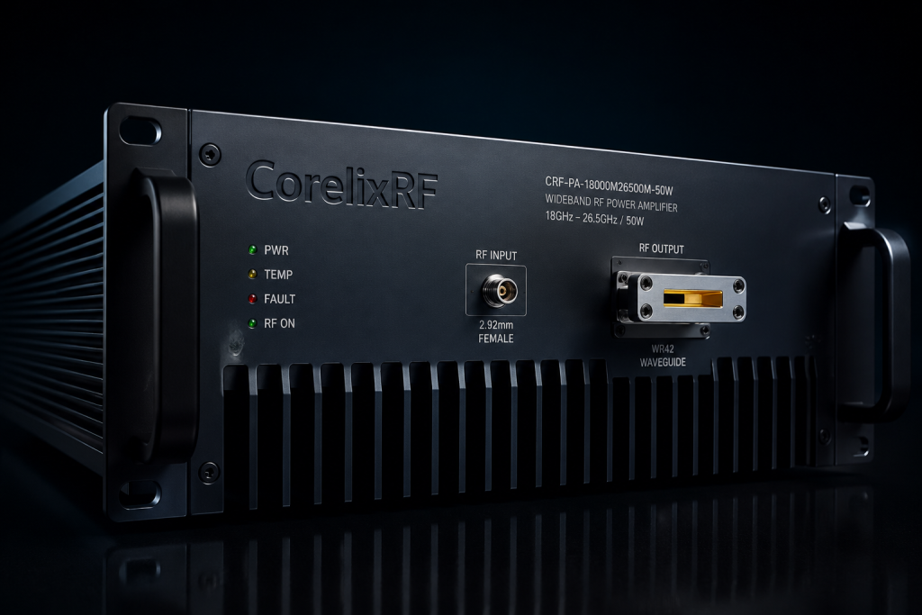
The CRF-PA-18000M26500M-50W tackles vehicle deployment problems head-on. Here is the exact secret. CorelixRF abandons standard thermal grease entirely for this model. We utilize military-grade Indium foil interfaces instead. Indium never suffers from any pump-out effect. It provides a permanent metallic thermal path. This unit features built-in over-temperature and over-voltage protection. Integrated VSWR monitoring prevents damage during mismatched antenna conditions. The heavy-duty 19-inch 3U chassis withstands extreme mechanical shock. Dedicated cooling fans force massive airflow across internal fins. This design guarantees stable performance across harsh vehicle environments. Consider three specific design advantages we implemented here. We used oversized heatsinks for maximum thermal mass. We incorporated dual redundant cooling fan banks. We utilized thick aluminum panels for structural rigidity. These choices guarantee absolute reliability under extreme duress.
Amplifier Protection Specs
| Protection Type | Trigger Condition | System Response |
| Over-Temperature | Heat sink > 85°C | Safe shutdown |
| High VSWR | Reflected power spike | Output limiting |
| Over-Voltage | Supply > 240V | Input isolation |
9. What are the key specifications of this 50W amplifier?
● Frequency range coverage
● Power output stability
● Control interface details
System integrators require precise engineering data for procurement. Let us examine this closely. This amplifier covers the 18,000 to 26,500 MHz band continuously. It delivers a guaranteed 50W rated output power consistently. Input VSWR stays strictly below 2:1 across all frequencies. Harmonic distortion remains firmly below -20 dBc during operation. Spurious emissions are tightly controlled under -60 dBc. Engineers can monitor operations via RS485 or LAN interfaces. Standard 2.92mm-Female and WR42 connectors guarantee reliable RF mating. Operating temperatures span from zero up to fifty degrees Celsius. Power consumption sits at 400W under full load. Three distinct application areas benefit from these specifications. Advanced test laboratories require extreme signal purity. Aviation control systems need absolute transmission reliability. Electronic communication platforms demand wideband frequency coverage. This unit serves all three rigorous engineering requirements.
10. How can system integrators implement this RF solution?
● Rack mounting procedures
● Interface connection guidelines
● Remote monitoring setup
Proper installation guarantees maximum hardware longevity. Please listen very closely now. Mount your 3U chassis securely using heavy-duty rails. Provide adequate clearance for front and rear air intake. Connect waveguide outputs using precision torque wrenches. Attach input cables carefully without over-tightening connectors. Connect RS485 control lines for remote telemetry access. Configure LAN interfaces for network-based system monitoring. Verify input power remains below 0 dBm before activation. Monitor built-in alarms during initial system commissioning. CorelixRF provides complete mechanical drawings for seamless integration planning. Three common installation mistakes destroy perfectly good amplifiers. Technicians often bend fragile RF cables sharply. Installers sometimes block critical rear cooling vents. Operators occasionally overdrive inputs past maximum ratings. Following our strict guidelines prevents these costly errors.
Thermal paste pump-out destroys vehicle-mounted RF amplifiers rapidly. CorelixRF eliminates this failure mode using advanced metallic interfaces. The CRF-PA-18000M26500M-50W guarantees sustained performance during harsh mechanical stress. Contact our engineering team today for full integration support. Robust hardware builds unshakeable confidence during serious field operations.
- Q1: What is thermal paste pump-out effect?
- Metal expansion differences force fluid compounds outward mechanically.
- Q2: How does mechanical vibration work?
- Constant physical shaking grinds thermal interfaces into dry powder.
- Q3: What causes frequent VSWR alarms?
- Harsh mechanical vibrations degrade internal thermal interfaces rapidly.
- Q4: Why do standard materials fail?
- Cheap greases lack sufficient particle density for vibration.
- Q5: How can engineers diagnose failures?
- Technicians utilize infrared cameras alongside forward power monitoring.
Make thermal interface reliability part of the delivery package
Thermal paste pump-out is easier to prevent when the RFQ includes vibration, thermal cycling, baseplate material, clamping method, duty cycle, power level and inspection criteria. Ask for the delivery evidence before release.
Recommended next step: send the operating band, target output power, duty cycle, thermal or load condition, control interface, protection behavior and required FAT documents. CorelixRF can review this thermal paste pump-out diagnosis requirement against standard amplifier platforms, RF front-end options and custom engineering constraints.