
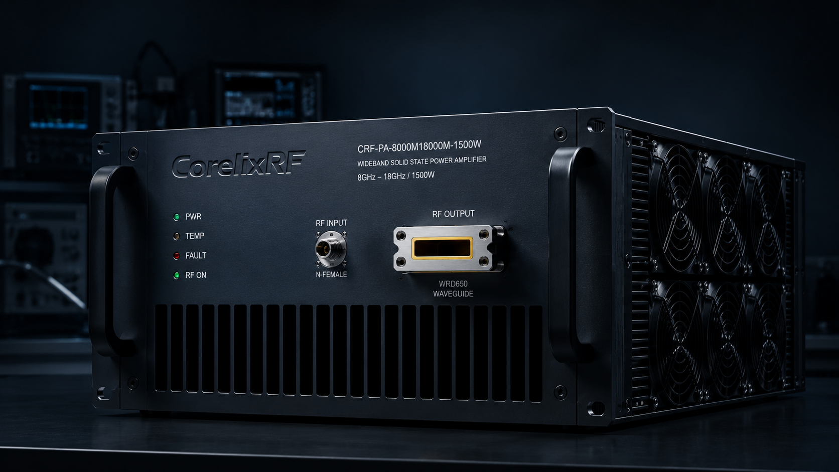
Primary engineering guide: this near-duplicate reference has been consolidated under How to Solve Thermal Paste Pump-Out Failures in High-Power GaN Systems?. Use the primary guide for the latest RF engineering review, compliance-safe wording, RFQ inputs and factory documentation path.
- Open the primary guide for the current topic cluster.
- Prepare RFQ inputs before requesting engineering review.
- Use the RF configurator to summarize band, power, interface and duty-cycle needs.
- Review delivery documentation for FAT-style evidence and shipment records.
- Contact CorelixRF when the project has a documented scope.
Archived page topic: How to Solve Thermal Grease Pump-Out Failures in Radar Systems?. This page remains available for reference, but search engines are pointed to the primary guide through canonical consolidation.
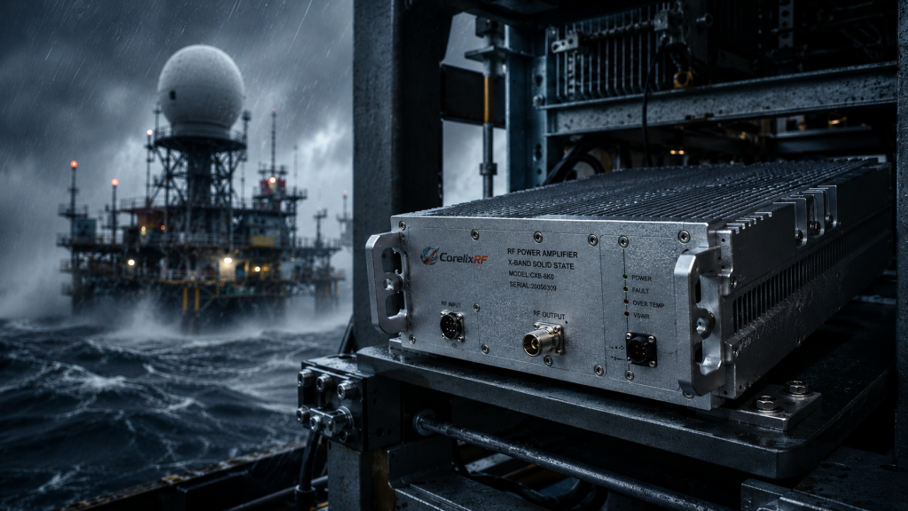
Equipment overheating constantly plagues offshore engineers. Radar system failures happen quickly without warning. You check your diagnostic panel. A sudden power drop appears alongside severe VSWR alarms. Salt spray and heavy diesel generator vibrations destroy generic thermal interfaces. Heat sink separation leaves your solid-state amplifier burning. Here’s the deal: precise mechanical matching stops thermal degradation completely. We developed a specific hardware architecture mitigating this exact failure mechanism. This solution utilizes direct metal-to-metal contact principles. CorelixRF brings 20 years of rigorous engineering experience addressing RF power amplifier issues.
1. What triggers thermal grease pump-out in offshore platform RF front-end systems?
Marine Environmental Stressors
Marine deployments present incredibly hostile physical operating conditions. A constant low-frequency rumbling originates from heavy onboard generators. You might be wondering: why does this matter for electronics? Daily temperature swings force metal housings into constant expansion cycles. GaN transistor baseplates expand at different rates than aluminum heat sinks.
The Physics of Mechanical Expulsion
This microscopic movement actively squeezes silicone-based thermal grease outwards. Engineers call this destructive physical action a pump-out effect. Over many months, this motion completely clears thermal paste from critical center hotspots. Microscopic air gaps replace highly conductive interface materials. Air acts as a fantastic thermal insulator. Such insulation creates localized catastrophic heat buildup directly underneath active RF dies. RF power modules suffer immediate thermal runaway under these exact circumstances. System integrators frequently misdiagnose this as pure component failure. True root causes always stem from inadequate mechanical interface planning. We see this specific mechanism ruining expensive hardware repeatedly.
| Material Type | Susceptibility to Pump-Out | Thermal Conductivity | Recommended Application |
| Standard Silicone Grease | High | Moderate | Benign indoor laboratory environments |
| Phase Change Material | Low | High | Marine and high-vibration systems |
| Indium Metal Foil | Zero | Very High | Extreme aerospace and military applications |
| Graphite Pad | Zero | Moderate | Low power industrial electronics |
2. How does the pump-out effect cause catastrophic thermal resistance increase?
Conduction Path Interruption
Thermal resistance dictates heat flow efficiency from die junction towards ambient air. A solid continuous path guarantees proper semiconductor cooling. What’s the real story? Pump-out physically breaks that crucial continuous conductive path. As thermal paste migrates toward outer edges, microscopic voids form. These tiny empty spaces block heat transfer severely. Thermal resistance jumps exponentially across those new air pockets.
Die-Level Degradation Physics
Operating junction temperatures climb dangerously past safe silicon operational limits. High heat directly degrades electron mobility within active transistor channels. Output power compresses well before reaching its rated maximum capacity. A module might normally push huge wattage effortlessly. Suddenly, it struggles outputting half that amount during continuous wave operation. Heat also shifts amplifier bias points unpredictably. Such shifting introduces severe intermodulation distortion into your transmission signal. Radar pulse fidelity deteriorates rapidly as module temperature spikes. High-power amplifiers require strictly managed thermal envelopes for linear operation. Uncontrolled thermal resistance increase ultimately triggers permanent hardware destruction. System MTBF drops drastically when engineers ignore thermal mechanics.
3. Why do standard thermal interface materials fail under marine vibration?
Chemical Breakdown Factors
Commercial grade greases utilize silicone oil bases heavily. Manufacturers design them for static servers inside climate-controlled data centers. Ready for the truth? Those compounds simply cannot handle offshore platform dynamics. Persistent mechanical shaking from deck machinery degrades grease viscosity fast. Constant churning separates conductive filler particles from their liquid binder. Salt-laden marine air accelerates chemical drying around exposed edges.
Cyclical Stress Failures
This crusty perimeter prevents fluid paste from migrating back inward. Normal thermal cycling then creates a unidirectional pumping action. Fluid pushes outward during heating phases but never returns upon cooling. Every single day removes a microscopic layer of conductive compound. A bare metal void remains after roughly six months of active deployment. Standard materials lack mechanical memory or restorative elasticity. They permanently deform under relentless cyclical stress. Engineering reliable systems requires entirely different heat dissipation philosophies. We completely abandon cheap silicone solutions for high-vibration environments.
| Deployment Duration | Observed Physical State | Electrical System Symptom |
| 1 Month | Normal paste distribution | Stable CW output power |
| 3 Months | Slight edge separation | Minor gain drift during operation |
| 6 Months | Visible center voids | High-frequency VNA curve collapse |
| 12 Months | Complete paste expulsion | Severe VSWR alarms and power shutdown |
4. What are the symptoms of pump-out induced failure in radar systems?
Diagnostic Warning Signs
Field engineers rarely notice thermal degradation during early operational phases. Initial diagnostics show perfect matching and expected output levels. Consider this fact: performance drops manifest slowly before accelerating wildly. Operators first observe dynamic gain drift across wide temperature swings. VNA measurement curves begin collapsing specifically at higher frequency bands. An offshore platform RF front-end module suddenly loses upper-band efficiency.
RF Parameter Collapse
Active onboard self-protection circuits might trigger false alarms frequently. A screen flash indicating sudden impedance mismatch confuses operators. Heat dramatically alters active device output capacitance. This capacitance shift detunes internal matching networks entirely. Output power reflects back inward instead of radiating outward. Technicians might swap antennas thinking external connections corroded. They completely miss an internal thermal disaster unfolding slowly. Measuring actual baseplate temperatures reveals localized hotspots exceeding 90 degrees Celsius. Such extreme heat signatures confirm total thermal interface collapse.
5. How does the CRF-PA-8000M18000M-1500W architecture prevent thermal degradation?
Phase Change Material Integration
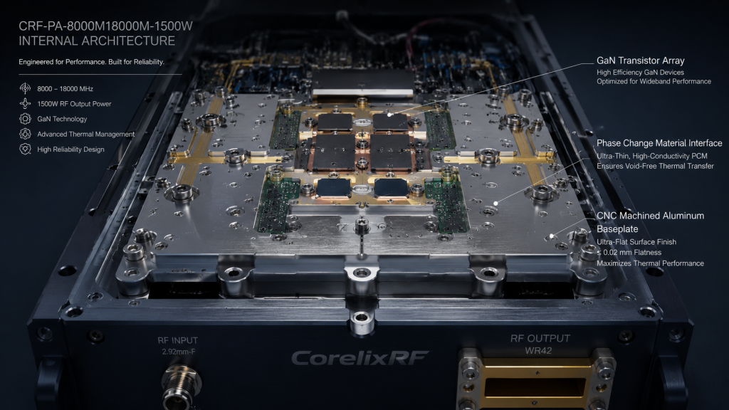
Solving mechanical failures requires strict hardware redesign from ground zero. CorelixRF attacks pump-out through superior structural rigidity and interface material selection. This changes everything: our CRF-PA-8000M18000M-1500W utilizes pure phase change materials. This specific model operates across 8,000 – 18,000 MHz seamlessly. We machine mating surfaces perfectly flat down towards extreme micrometer tolerances. These ultra-flat surfaces minimize any necessary gap-filling volume significantly. Less interface material means less material available for outward migration.
Aerospace Clamping Techniques
Phase change pads soften at operating temperatures without becoming fluid. They conform perfectly under heavy mounting pressure. High-tension aerospace bolts maintain constant downward clamping force permanently. This calculated pressure prevents micro-movements between amplifier housings and cooling structures. Salt fog cannot penetrate these tightly clamped boundaries. Our architecture essentially welds heat generating components directly against cooling fins thermally. We guarantee zero pump-out effect over a twenty-year marine lifespan.
| Parameter | Specification | Notes |
| Frequency Range | 8,000 – 18,000 MHz | Covers X and Ku bands |
| Rated Output Power | 1,500 W | GaN technology based |
| Nominal Gain | 62 dB | Flatness -6 to 6 dB |
| Input VSWR | 1.5:1 | 50 Ω system |
6. What engineering design ensures 1500W stable output across 8000-18000 MHz?
Broadband Power Generation
Generating massive broadband energy requires incredible electrical and thermal stability. The CRF-PA-8000M18000M-1500W achieves a rated output power of 1,500 W. Pushing wideband frequencies from 8,000 up towards 18,000 MHz stresses components deeply. Let’s get down to business: managing internal heat flow remains our absolute priority. This unit consumes significant current from an AC 380V supply. Such massive power consumption translates into immense localized heat density.
Internal Thermal Management
Our engineers designed advanced spatial combining networks minimizing insertion loss. Lower RF losses directly translate into less wasted thermal energy. A built-in high-efficiency air cooling system moves massive air volumes constantly. Heavy-duty cooling fans resist salt corrosion and bearing wear perfectly. Solid GaN transistors handle high junction temperatures inherently well. However, our zero-void thermal interface keeps them running remarkably cool. This thermal headroom guarantees strict linearity across complex electronic warfare signals. You get reliable 62 dB gain without thermal compression artifacts.
7. How do strict structural flatness tolerances eliminate air gaps permanently?
CNC Machining Tolerances
Mechanical precision directly dictates electrical reliability within high-power assemblies. A wavy baseplate surface spells doom for thermal conductivity. Think about it: microscopic hills and valleys create massive localized heat traps. We CNC machine every single chassis component from solid metal billets. Our factory ensures surface flatness exceeding strict aerospace laboratory standards. This extreme flatness allows metal-to-metal contact across most mating areas.
Structural Rigidity Benefits
Remaining microscopic voids require very little phase change material filler. Less compressible material guarantees a rigid, unmoving mechanical joint. Continuous vibration from marine engines cannot shift this tightly bound structure. A completed assembly behaves thermally like one single solid metallic block. We secure modules using precisely torqued steel fasteners. These fasteners maintain elastic tension regardless of ambient temperature fluctuations. You never experience loose screws causing sudden thermal spikes. Engineering truth always favors rigid mechanical foundations over cheap chemical patches.
| Machining Feature | Tolerance Standard | Thermal Impact |
| Baseplate Flatness | < 0.02 mm per 100 mm | Maximizes direct metal contact |
| Surface Roughness (Ra) | < 0.8 micrometers | Prevents thick grease pooling |
| Bolt Torque Variance | < 2% | Ensures uniform clamping pressure |
| Chassis Rigidity | High (Solid Aluminum Billet) | Resists vibrational flexing |
8. Why is VSWR protection critical when thermal resistance fluctuates?
Real-Time VSWR Monitoring
Antenna systems on ocean rigs suffer severe weather abuse constantly. Ice buildup or salt corrosion ruins external impedance matching suddenly. Now, listen closely: reflected power hitting a hot amplifier causes instant destruction. A degraded thermal interface leaves transistors highly vulnerable. The CRF-PA-8000M18000M-1500W features comprehensive built-in protection circuitry. It actively monitors over-voltage, over-temperature, over-drive and VSWR conditions. An amplifier handles a 1.5:1 input VSWR safely without tripping.
Automated Survival Protocols
If external loads fail catastrophically, internal sensors react within microseconds. Internal logic shuts down drive power before standing waves destroy GaN dies. Monitoring real-time temperatures prevents cascaded failures if cooling fans stall. A rugged WRD650 output connector handles massive RF voltages without arcing. These layers of defense ensure survivability during worst-case scenario operations. A sudden antenna cable break will not cause internal fires. We design for environments where maintenance access remains impossible for months. Technicians cannot simply fly via helicopter during heavy storms. System integrators sleep well knowing hardware protects itself autonomously. Robust digital control networks alert shoreside operators immediately.
9. How does CorelixRF validate long-term thermal reliability for marine deployments?
Brutal Environmental Chambers
You cannot fake true engineering durability using basic laboratory simulations. Real validation requires subjecting hardware towards absolute physical extremes constantly. Look at the data: our testing protocols destroy weakly designed prototypes routinely. We place finished units inside specialized environmental cycling chambers. These chambers simulate rapid freezing and boiling temperature swings rapidly. Powerful shaker tables simulate decades of heavy diesel engine vibration continuously. We measure thermal resistance before, during, and after these brutal tests.
Verifiable Data Deliverables
Any tiny degradation regarding heat transfer means immediate design rejection. We monitor harmonic outputs meticulously, ensuring they stay below -15 dBc. Spurious emissions must remain strictly below -60 dBc throughout testing. Only architectures displaying absolutely zero parameter drift pass our factory gates. We supply exact test data and pattern files for project review. You receive comprehensive reports validating every single performance metric. This transparency proves our solutions survive actual ocean deployment scenarios. Engineers reviewing our documentation see unvarnished truth regarding power limits. We sell engineered reality rather than hopeful marketing promises.
| Test Category | Methodology | Pass/Fail Criteria |
| Thermal Shock | -40°C to +85°C rapid transition | Zero gain drift, zero grease pump-out |
| Vibration Profiling | Random and sinusoidal shaking | Structural integrity maintained |
| RF Burn-in | 72 hours continuous rated output | Stable 1500W CW, normal temperatures |
| Protection Verification | Deliberate output mismatch (Open/Short) | Autonomous shutdown without damage |
10. What steps should system integrators take for offshore platform RF front-end maintenance?
Remote Telemetry Implementation
Preventative maintenance strategies change drastically when deploying zero-maintenance hardware designs. You no longer need routine shutdowns for thermal paste reapplication. Here’s the kicker: intelligent monitoring replaces dangerous physical intervention completely. Integrators must utilize our built-in RS485 or LAN control interfaces heavily. These digital connections provide real-time telemetry regarding internal module health. Engineers can track baseplate temperatures precisely without opening sealed equipment racks.
Eliminating Physical Interventions
You monitor forward and reverse power metrics continuously. Setting custom alarm thresholds alerts shoreside teams before critical failures occur. If temperature delta slowly rises, structural mounting might need inspection. You avoid touching delicate RF connectors unnecessarily during routine checks. Eliminating human intervention prevents accidental contamination of weather-sealed radar enclosures. Smart remote monitoring saves massive logistical costs regarding helicopter maintenance flights. Proper integration ensures our hardware functions perfectly for decades straight.
Thermal grease pump-out destroys expensive offshore RF platforms silently. Combining rigid structural engineering with advanced phase change materials eliminates this threat. The CRF-PA-8000M18000M-1500W provides a rugged, mathematically proven thermal solution. Contact CorelixRF engineering teams requesting detailed performance datasheets today.
FAQ Section
- Q1: What triggers thermal grease pump-out in RF systems?
- Constant low-frequency generator rumbling and daily temperature swings force metal housings into expansion cycles. This movement actively squeezes silicone-based thermal grease outwards. Microscopic air gaps replace conductive paste eventually.
- Q2: How does a pump-out effect cause catastrophic thermal resistance increase?
- Pump-out physically breaks that crucial continuous conductive path. Tiny empty spaces block heat transfer severely. Operating junction temperatures climb dangerously past safe silicon limits.
- Q3: Why do standard thermal interface materials fail under marine vibration?
- Commercial greases utilize silicone oil bases meant for static servers. Persistent mechanical shaking degrades grease viscosity fast. Salt-laden marine air accelerates chemical drying around exposed edges.
- Q4: What are typical symptoms indicating pump-out induced failure?
- Operators first observe dynamic gain drift across wide temperature swings. VNA measurement curves begin collapsing specifically at higher frequency bands. Severe VSWR alarms trigger frequently.
- Q5: How does our CRF-PA-8000M18000M-1500W prevent thermal degradation?
- Our architecture utilizes pure phase change materials alongside ultra-flat machined surfaces. High-tension aerospace bolts maintain constant downward clamping force permanently. This prevents micro-movements between amplifier housings and cooling structures entirely.
Turn this RF requirement into a quotable specification
Use this article as a starting point for a buildable RF specification. Before quoting, CorelixRF normally checks frequency range, output power, gain flatness, duty cycle, load mismatch, thermal path, control interface, enclosure limits and acceptance data.
- thermal reliability articles – continue with related thermal drift, cooling and sealed-enclosure reliability notes
- RF power amplifier platforms – match the article topic to available RF power amplifier families
- solid state power amplifier page – review SSPA architecture when reliability and repeatable test data matter
- RFQ checklist – send the data buyers usually forget, including band, power, duty cycle, interface and test standard
- delivery documentation – check what documents can support incoming inspection, FAT review and long-term maintenance
- case studies – review similar engineering paths before sending an RFQ
- engineering contact – send the application notes, block diagram or target specification to engineering sales
For a faster review, send operating band, power target, modulation or waveform, antenna/load condition, cooling limit, mechanical envelope and target test standard through the RFQ or contact path.