
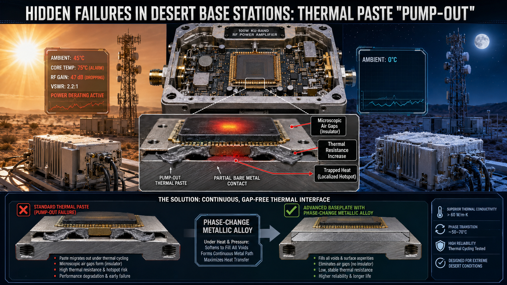
Hidden Failures in Desert Base Stations: Thermal Resistance Increase Due to Thermal Paste “Pump-out” After Long-Term Service. Field engineers constantly fight severe hardware degradation operating within arid remote networks. Daily thermal cycling forces interface materials outward drastically raising device temperatures until catastrophic failure occurs. Here is the deal. We fix this exact mechanical degradation using robust hardware architecture found inside specific GaN modules. Two decades spent troubleshooting high-frequency hardware provide concrete data proving how physical design dictates long-term survival.
1. What causes thermal paste pump-out inside desert base stations?
● Environmental Thermal Cycling
● Mechanical Pumping Action
● Interface Material Degradation
System Level Thermal Physics
Desert environments subject communication hardware equipment towards extreme diurnal temperature shifts daily. Ambient air might reach forty-five degrees Celsius during midday while dropping near freezing after dark. This constant expanding alongside contracting creates massive mechanical pumping action against internal interface materials. Silicone-based greases migrate outward from under high-power amplifier chips over several months continuously. Such migration leaves microscopic air gaps separating bare metal surfaces physically. You might be wondering. Air acts as a fantastic thermal insulator rather than an effective conductor. Heat generated by power transistors becomes trapped locally raising core junction temperatures beyond safe operating limits. System management software eventually flags an over-temperature alarm when die temperatures hit critical thresholds. We consistently see remote radio units dropping transmit power automatically trying vainly saving expensive internal components. Physical hardware degradation always overrides software management attempts eventually.
| Thermal Parameter | Day Condition | Night Condition | Physical Effect |
| Ambient Air | 45 C | 0 C | Massive structural shifting |
| Chassis Metal | Expanded | Contracted | Surface grinding action |
| Thermal Paste | Viscous liquid | Hardened | Outward lateral migration |
| Interface State | Bonded | Gapped | Conductive failure |
2. How does diurnal temperature variation degrade RF amplifier performance?
● Gain Flatness Collapse
● Power Added Efficiency Drop
● Noise Floor Spikes
RF Gain and Efficiency Collapse
Amplifier performance degrades predictably whenever trapped heat raises internal die temperatures excessively. We observe significant drops concerning output gain alongside collapsing power added efficiency metrics. A system originally pushing fifty decibels of gain struggles delivering expected parameters suddenly. Electrons scatter more frequently inside semiconductor lattices operating under high thermal stress continuously. This scattering reduces carrier mobility directly impacting RF amplification capabilities noticeably. Base station controllers detect this fading output prompting them driving higher input signals into struggling modules. But here is the kicker. Pushing harder only generates more heat accelerating an unavoidable downward spiral rapidly. Output spectrums begin showing elevated noise floors exceeding negative forty decibels per megahertz quickly. Intermodulation distortion spikes ruin signal integrity completely rendering data transmission impossible. Field technicians arriving onsite often find blistered paint near heatsink fins while internal telemetry reports complete thermal runaway.
3. Why do traditional cooling solutions fail inside 10.7-12.7 GHz systems?
● High Frequency Power Density
● Mechanical Flexing Under Load
● Localized Hotspot Generation
Frequency Specific Power Density
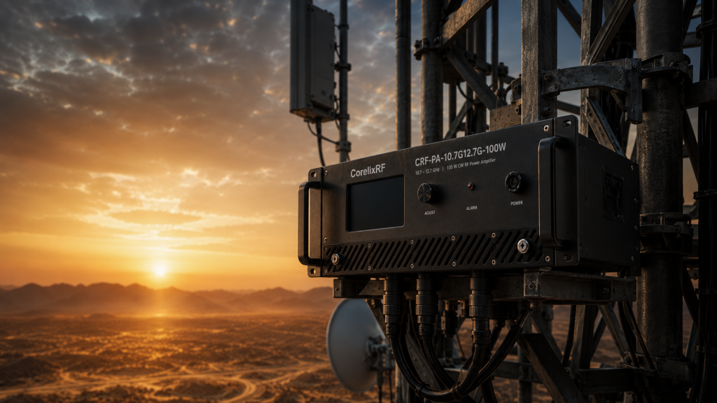
High-frequency modules operating within Ku-band spectrums demand incredibly dense power packaging physically. Operating across 10,700-12,700 MHz bands requires tightly spaced component layouts minimizing parasitic inductance. Squeezing hundred-watt rated power outputs into compact enclosures creates massive concentrated thermal hotspots. Standard aluminum heatsinks paired alongside cheap thermal compounds cannot transfer heat fast enough away from localized zones. What is the real story? Cheap pastes dry out rapidly under continuous heavy thermal loading conditions. Once volatile compounds evaporate completely, remaining solid particles crumble away under normal operational vibrations. Desert winds buffeting tower structures add mechanical stress twisting chassis assemblies slightly. This microscopic flexing further grinds degraded interface materials into useless dust completely. Traditional air cooling methods fail when that critical conductive bridge disappears leaving components isolated. We need advanced metallic phase-change materials or precisely machined direct-die attachment methods resolving this physical disconnect.
| Failure Stage | Diagnostic Symptom | Instrument Used | Corrective Action |
| Initial | Elevated casing temp | Thermal Imager | Monitor telemetry |
| Intermediate | Gain drop 2.5 dB | Network Analyzer | Schedule site visit |
| Severe | VSWR Alarm triggers | NMS Software | Replace thermal path |
| Critical | Output drops to zero | Spectrum Analyzer | Swap hardware module |
4. What diagnostic tools identify hidden thermal resistance increases?
● Thermal Imaging Analysis
● Vector Network Assessment
● Current Draw Monitoring
Frontline Troubleshooting Tactics
Diagnosing thermal pump-out requires looking past software alarms directly at physical hardware symptoms. Engineers use thermal imaging cameras scanning external chassis surfaces searching for unusual cold spots. A heatsink running surprisingly cool while internal telemetry screams about overheating indicates total thermal interface failure. Heat cannot reach those cooling fins anymore leaving components frying internally. Network analyzers placed inline frequently reveal collapsed high-frequency response curves validating physical destruction. This is where it gets interesting. Technicians measuring return loss see severe impedance mismatches developing as transistors warp physically. We monitor current draw closely using clamp meters during diagnostic runs observing system efficiency. Modules pulling thirty amps at twenty-eight volts but outputting terrible RF power indicate massive energy converted purely into wasted heat. Catching these hidden failures early prevents expensive total system replacements across remote desert deployments.
5. How does thermal pump-out trigger VSWR alarms and power derating?
● PCB Structural Warping
● Transmission Line Disruption
● Active Protection Engagement
Hardware Protection Triggers
Modern amplification modules incorporate built-in protection circuitry preventing immediate destruction during fault conditions. Thermal paste degradation slowly increases internal resistance until components reach defined trip points. Our hardware monitors reverse power constantly looking for sudden antenna mismatches or reflected energy. Extreme heat physically distorts internal printed circuit boards slightly warping rigid substrate layers. This micro-warping disrupts fifty-ohm transmission lines causing internal signal reflections instantly. Think about it. Reflected energy compounds existing thermal problems quickly destroying delicate amplifier stages. Protection logic detects this rising voltage standing wave ratio triggering automatic power derating protocols. Output drops dramatically trying minimizing internal stress protecting surviving semiconductor junctions. Site operators often misdiagnose these events blaming external antenna damage initially without investigating further. We dispatch crews checking feeder cables only finding perfect external connections instead. True engineering requires understanding these cascading failure mechanisms completely avoiding useless maintenance loops.
| Protection Feature | Trigger Condition | System Response | Hardware Component |
| Over-temperature | Core > 50 C | Current limiting | Thermistor |
| Over-voltage | Supply > 28V | Cutoff sequence | Voltage regulator |
| VSWR Mismatch | Ratio > 2:1 | Power derating | Directional coupler |
| Over-drive | Input > 0 dBm | Gain reduction | Input attenuator |
6. What role does GaN technology play mitigating extreme thermal stress?
● Superior Thermal Conductivity
● High Junction Tolerances
● Efficiency Safety Margins
Gallium Nitride Advantages
Gallium Nitride substrates offer fundamentally superior thermal conductivity compared against legacy silicon alternatives. GaN devices handle significantly higher junction temperatures without suffering immediate catastrophic degradation events. This advanced semiconductor material allows engineers pushing hundred-watt continuous outputs reliably across wide bandwidths. Higher efficiency means less raw DC power converts into useless heat requiring massive dissipation. Look at the data. Pumping twenty-eight volts into highly efficient GaN structures yields cleaner RF output across challenging frequencies. We design systems utilizing these specific thermal properties anticipating harsh desert realities actively. Even if interface materials degrade slightly over several years mechanically, GaN components survive conditions destroying older technologies instantly. Robust intrinsic material properties provide vital safety margins protecting expensive remote installations continuously. Desert networks demand this exact level of foundational physical resilience maintaining critical communication links.
7. How do WR75 output connectors perform under thermal expansion?
● Waveguide Shear Forces
● Impedance Stability Requirements
● Environmental Seal Integrity
Waveguide Mechanical Integrity
High-power RF exits amplification stages traversing specialized mechanical waveguide structures safely. Output connectors handle massive energy transfers precisely while facing extreme environmental variations constantly. Desert heat causes different metals expanding at unequal rates across structural boundaries creating friction. Mismatched expansion coefficients create immense mechanical shear forces threatening delicate RF transitions severely. Now consider this. We engineer flanges absorbing microscopic shifts without altering critical internal waveguide dimensions. A warped waveguide instantly creates horrific impedance mismatches throwing reflected power backward into sensitive electronics. Maintaining flat gain across two gigahertz bandwidths requires absolute mechanical stability preventing phase distortion. Precise machining tolerances guarantee tight seals preventing fine desert sand entering microwave cavities unexpectedly. Reliable physical connections dictate continuous field operation long after installation crews depart remote tower sites.
| Interface Point | Connector Type | Expansion Risk | Engineering Mitigation |
| RF Input | SMA-Female | Low | Threaded tension lock |
| RF Output | WR75 | High | Precision milled flange |
| DC Power | Multi-pin | Medium | Floating pin sockets |
| Control Data | RS485 | Low | Encapsulated housing |
8. What engineering mechanisms prevent over-temperature within 100W modules?
● Active Thermistor Monitoring
● Rapid Current Limiting
● Telemetry Data Reporting
Integrated Active Protection
Handling one hundred watts of rated output power requires sophisticated internal management logic constantly. Hardware must react faster than human operators whenever thermal situations deteriorate dangerously quickly. Our designs incorporate multiple thermistors placed strategically directly near active heat sources monitoring conditions. These sensors feed real-time analog data into rapid-response protection microcontrollers making split-second decisions. Ready for the good part? If temperatures exceed fifty degrees Celsius unexpectedly, control loops engage active current limiting instantly. Built-in protection logic throttles performance gracefully instead of suffering violent sudden death silently. We implement strict over-voltage alongside over-drive safeguards catching cascading failures early preventing catastrophic chain reactions. RS485 control interfaces report detailed telemetry allowing network operations centers seeing exact physical states remotely. This transparency stops blind dispatching letting maintenance teams prepare correct replacement parts beforehand saving valuable time.
9. How does the CRF-PA-10700M12700M-100W solve thermal pump-out physically?
● Phase-Change Metallic Alloys
● Precision Milled Baseplates
● Factory Burn-in Protocols
Advanced Baseplate Architecture
Our specific module abandons generic thermal pastes favoring advanced phase-change metallic alloys completely. These specialized materials liquify slightly during operation filling microscopic voids perfectly creating seamless thermal pathways. They solidify again during cooling cycles without pumping outward from underneath hot components mechanically. We machine baseplates extremely flat reducing necessary gap filler thickness significantly improving thermal transfer rates. Here is the deal. Thinner interface layers mean vastly reduced total thermal resistance across entire operating envelopes. Such hardware maintains strict gain flatness across entire operating bands because core temperatures remain stable. Built entirely around advanced GaN technology, it operates comfortably within demanding desert environments flawlessly. Rigorous factory burn-in testing forces aggressive thermal cycling identifying weak bonds before field deployment happens. We deliver predictable physical reality rather than empty marketing promises protecting client investments.
| Parameter | CRF-PA-10700M12700M-100W Spec | Engineering Benefit |
| Frequency | 10,700-12,700 MHz | Covers full Ku-band |
| Rated Power | 100 W | High penetration capability |
| Gain | 50 dB | Minimizes pre-amp needs |
| Noise Floor | -40 dBm/MHz | Preserves signal integrity |
| Impedance | 50 Ω | Prevents internal reflections |
10. What are long-term reliability metrics for desert-deployed RF systems?
● Mean Time Between Failures
● Operational Expense Reduction
● Spectral Purity Maintenance
Lifecycle Performance Data
True engineering success manifests through decades of boring continuous operation out in miserable locations. We track failure rates obsessively measuring mean time between failures across thousands of deployed units. Proper thermal management drastically reduces component aging extending useful lifecycles predictably generating higher return on investment. Systems utilizing robust interface materials show practically zero gain drift over five years operating continuously. What is the real story? Less truck rolls save massive operational expenses across sprawling desert networks significantly. Replacing a single tower amplifier costs thousands regarding labor alone before purchasing replacement hardware. We specify fifty-ohm impedance stability strictly because physical degradation ruins network timing synchronization completely. Maintaining negative sixty decibel spurious emissions requires pristine hardware health throughout extended service lives continuously. Concrete physical design choices dictate financial profitability directly proving solid engineering matters most.
Conclusion Solving hidden thermal pump-out failures requires respecting fundamental thermodynamics alongside rigorous RF engineering practices completely. The CRF-PA-10700M12700M-100W provides a robust physical solution addressing severe desert environmental challenges directly. System integrators should analyze thermal interface material properties strictly during initial component selection phases preventing future outages. Contact CorelixRF engineering teams requesting detailed application notes regarding extreme environment deployment strategies immediately.
FAQ Section
Q1: What is thermal pump-out?
Thermal pump-out represents a mechanical degradation process where extreme temperature cycling forces thermal interface grease outward from between hot components and heatsinks. This physical movement leaves insulating air gaps causing severe localized overheating. Desert environments subject hardware modules towards massive diurnal temperature swings daily. Expanding metallic surfaces grind against contracting layers physically pushing viscous pastes away from central hotspots. Bare metal separating creates microscopic voids acting like thermal insulators. Device junctions overheat rapidly once conductive pathways disappear completely. True engineering eliminates this failure mode utilizing phase-change alloys instead.
Q2: How does thermal degradation affect RF signals?
Trapped heat lowers semiconductor carrier mobility directly reducing amplifier gain. Output power drops while intermodulation distortion spikes heavily ruining signal integrity. Excessive heat physically warps internal printed circuit boards creating impedance mismatches reflecting energy backward. System controllers detect dropping performance pushing higher input signals attempting compensation blindly. This forced overdrive generates additional thermal waste accelerating catastrophic hardware failure rapidly. Network analyzers placed inline show collapsed high-frequency response curves validating physical destruction. Engineers arriving onsite find blistered paint proving massive internal thermal runaway events.
Q3: Why do desert environments accelerate hardware failure?
Deserts feature massive temperature swings between blazing hot days alongside freezing nights. This constant rapid expanding alongside contracting mechanically grinds traditional thermal pastes into useless dust quickly. Fine sand blowing continuously adds physical abrasion threatening external waveguide seals constantly. High ambient temperatures eliminate natural convective cooling margins forcing hardware running near maximum thermal limits continuously. Any minor increase regarding internal resistance pushes junction temperatures beyond safe operating thresholds instantly. Remote locations delay maintenance responses allowing minor degradation escalating into total system destruction unnoticed.
Q4: Can software fix thermal resistance increases?
No software algorithm fixes broken physical thermal pathways successfully. Management systems only reduce transmit power attempting survival through active derating protocols. Throttling current draw drops heat generation temporarily avoiding immediate fires. True resolution requires replacing failed interface materials using advanced metallic phase-change alternatives during manufacturing. Relying upon logic loops ignoring fundamental thermodynamic realities guarantees eventual network outages. Telemetry data provides diagnostic clues pointing towards physical repairs rather than virtual solutions. Proper hardware architecture remains absolutely necessary preventing field failures.
Q5: Does GaN technology eliminate cooling requirements?
Gallium Nitride handles higher temperatures efficiently but still requires robust physical cooling paths. It provides vital safety margins surviving harsh conditions longer than older silicon components facing identical thermal interface degradation. High efficiency means less consumed energy converts into wasted heat requiring dissipation. Pushing one hundred watts continuously demands precisely machined baseplates mating flawlessly against external heatsinks. Engineers must design comprehensive thermal management systems respecting GaN capabilities without ignoring basic thermodynamic laws. Rugged physical construction dictates ultimate field reliability across remote deployments.
Turn VSWR behavior into factory acceptance evidence
High VSWR protection should be defined with mismatch scenario, foldback or shutdown threshold, recovery logic, alarm output, thermal limit and FAT evidence. This makes protection claims measurable for procurement.
Recommended next step: send the operating band, output power target, duty cycle, load condition, control interface, protection or thermal limits and required FAT documents. CorelixRF can review this How to Fix RF Amplifier Thermal Failure and Resolve VSWR Alarms? requirement against standard RF amplifier platforms, RF front-end options and controlled customization paths.