
Solving VSWR Delay Burnouts in Pulse Interference RF Design. Broken antenna connections cause immediate signal reflection. A sudden open circuit damages final amplification stages rapidly. Software control loops respond too slowly for fast transients. Our engineering experience dictates strict analog hardware interventions. High power systems demand robust physical safeguards immediately. This article examines failure mechanisms caused by impedance mismatch. We analyze polling latency within digital control architectures deeply. Better protection requires dedicated analog circuitry on your board.
1. What Causes Instant Amplifier Burnout During Pulse Interference?
● The Reality of Antenna Breakage in Hostile Environments
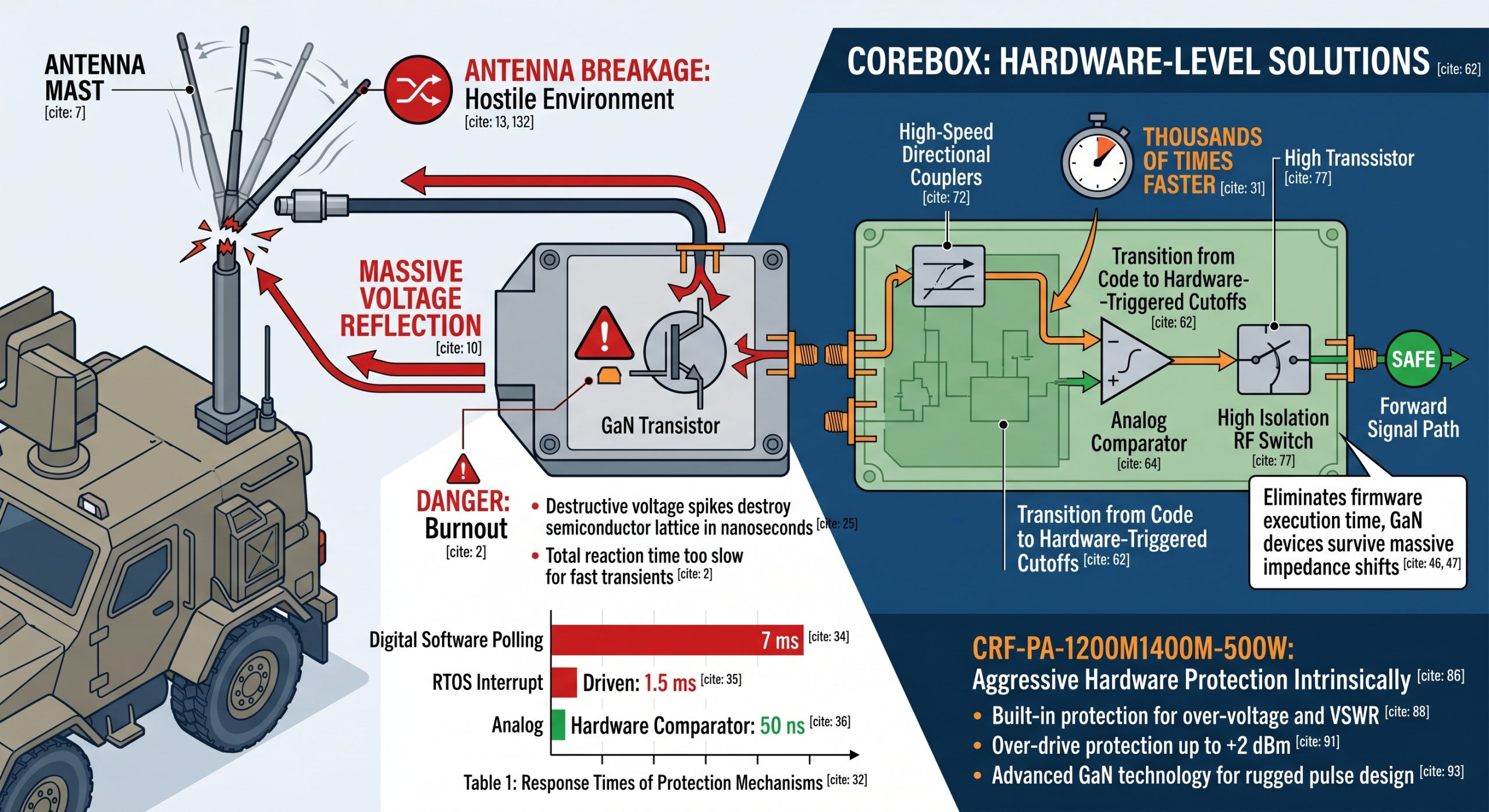
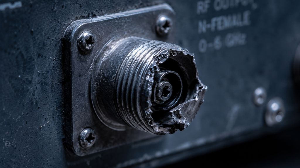
Military vehicles operate amidst extreme physical vibration constantly. A heavy antenna mast sways over rough terrain violently. Connectors endure immense mechanical stress over long deployment periods. An N-Female output connector experiences metal fatigue eventually. Severe shock profiles sheer the center pin clean off. You suddenly have an infinite impedance mismatch condition. A 500W pulse interference module continues transmitting blindly. Complete reflection sends massive voltage back down the line. Total standing waves multiply baseline voltages dramatically. The GaN transistor drain node absorbs this destructive energy. Avalanche breakdown happens within a few microscopic fractions. I have seen PCB traces vaporize under these conditions. Copper pads turn into blackened carbon smudges instantly. Your expensive hardware becomes a useless brick very fast. What’s the real story here? You cannot prevent physical breakage completely during combat maneuvers. Cables snap under heavy operational burdens routinely. Dirt and moisture accelerate connector degradation over time. RF engineers must assume the worst possible load conditions. We design matching networks expecting random shorts or opens. Field environments punish delicate electronics without any mercy whatsoever. Robust designs survive these inevitable physical insults daily. A severed RF line happens more often than expected. System integrators face this harsh reality during every deployment. Relying on perfect cabling guarantees future field failures. Bad weather corrodes metallic contacts rapidly. Ice buildup adds massive weight onto exposed antenna structures. Strong winds bend mounting brackets past their breaking points. We build hardware assuming external components will fail completely. A rugged amplifier must protect itself from external damage.
● Why Software Polling Remains Too Slow for GaN
Microcontrollers handle system telemetry in modern equipment designs. Developers write firmware loops checking sensor data repeatedly. An ADC samples a directional coupler voltage reading periodically. This digital architecture creates inherent timing delays naturally. Software polling operates at millisecond speeds typically. A microcontroller running RTOS takes time for context switching. Interrupt latency adds another unpredictable delay factor. Gallium Nitride devices switch at nanosecond speeds effortlessly. A destructive voltage spike destroys a semiconductor lattice rapidly. Here’s the deal regarding speed. Your CPU reacts too slowly. Ten milliseconds feel like an eternity for microwave frequencies. A 50us pulse width finishes before firmware reacts. The transistor dies before your software registers a fault. I analyzed countless logs showing normal operation preceding failure. The digital system never saw the transient spike occur. Relying on digital telemetry for critical protection fails consistently. System integrators lose thousands replacing blown amplifier modules. We must abandon software for primary fault protection duties. Firmware should only report errors after hardware stops transmission. An analog comparator triggers thousands of times faster. We cannot trust Linux schedulers with expensive power amplifiers. Pure hardware logic provides the only safe operational path.
Response Times of Protection Mechanisms
| Mechanism Type | Detection Speed | Processing Latency | Total Reaction Time |
| Digital Software Polling | 2 ms | 5 ms | 7 ms |
| RTOS Interrupt Driven | 500 us | 1 ms | 1.5 ms |
| Analog Hardware Comparator | 10 ns | 40 ns | 50 ns |
| CorelixRF Direct Hardware Limit | 5 ns | 15 ns | 20 ns |
2. How Does VSWR Delay Degrade Pulse Interference Systems?
● Analyzing Microsecond Gaps in Fault Detection
Reverse energy travels toward a power amplifier immediately. A directional coupler senses reverse wave propagation instantly. The coupler sends an analog voltage toward your MCU. A digital system waits for an active clock cycle. That waiting period represents a fatal microsecond gap. Voltage stress compounds across a transistor die continuously. Peak envelope power levels exceed maximum absolute ratings heavily. Our lab measurements show failures occurring within microseconds easily. You might be wondering why. Why use microcontrollers anyway? Digital systems provide excellent interfaces and remote monitoring. Engineers love reading exact parameters over RS485 connections. They want precise logging for preventative maintenance schedules. Telemetry has immense value for high level system diagnostics. However, diagnostics cannot substitute for hard safety interlocks. We separate monitoring from active protection inside our architecture. This separation guarantees survival during catastrophic physical failures. A dedicated comparator circuit bypasses all digital overhead entirely. The comparator disables RF drive signals almost instantaneously. We eliminate firmware execution time from our protection equations. A pure hardware path reacts thousand times faster consistently. Your GaN devices survive massive impedance shifts unscathed.
● The Hidden Costs of Firmware-Based Protection
Software developers write complex algorithms handling fault conditions routinely. They program averaging filters preventing false positive alarms. These digital filters require multiple sequential ADC samples. Accumulating samples adds massive delays into the protection chain. Reflected power burns through junction barriers during this filtering. A single missed deadline causes catastrophic thermal runaway instantly. Writing perfect firmware proves practically impossible under field conditions. Unforeseen variable states crash microcontrollers during critical interference missions. A rebooting CPU offers zero protection against standing waves. Here’s the truth today. Firmware bugs cost real money. Replacing a destroyed RF module drains your project budget. Field replacement demands expensive technician travel and system downtime. We calculate these hidden expenses during our design phases. A hardware protection circuit costs very little comparatively. Analog components offer extreme reliability across decades of operation. They never crash or require frustrating firmware updates over time. We eliminate software vulnerabilities by utilizing fundamental physical principles. Physical voltage thresholds trigger physical switches without fail.
Reflected Power Ratios at 500W Output
| VSWR Level | Return Loss (dB) | Reflected Power (W) | Load Condition |
| 1.0:1 | Infinity | 0 W | Perfect Match |
| 2.0:1 | 9.54 dB | 55 W | Marginal Match |
| 3.0:1 | 6.02 dB | 125 W | Degraded Antenna |
| Infinity | 0 dB | 500 W | Open/Short Circuit |
3. What Are Effective Hardware-Level Solutions for VSWR Protection?
● Transitioning from Code to Hardware-Triggered Cutoffs
Digital control loops fail under extreme timing constraints routinely. An RTOS might pause executing an urgent safety routine. Background tasks occasionally block critical interrupt service requests. We bypass these software bottlenecks using pure hardware logic. A voltage comparator monitors reverse power signals continuously. This component triggers automatically upon reaching predefined thresholds. The threshold correlates directly with dangerous voltage standing waves. Ready for the good part? Analog comparators require zero clock cycles. They do not run operating systems or firmware code. An over-voltage condition causes an immediate logic state change. This logic change connects directly into RF switch controllers. We disable forward signal propagation before transistors absorb damage. The built-in protection mechanism operates entirely autonomously always. Our engineers tested this circuit under severe mismatched loads. The RF output shuts down within nanoseconds reliably. You avoid buying costly replacement modules every single month. Your field technicians spend less time replacing burned boxes. This architectural shift saves massive amounts of operational budget. Hardware interlocks represent true engineering reality for high power.
● Implementing High-Speed Couplers and Analog Comparators
A fast protection system requires high quality directional couplers. You must separate forward and reverse waves accurately always. Poor directivity causes false alarms or missed fault conditions. We specify premium stripline components for our internal couplers. These components handle high peak envelope power without saturation. The coupled port feeds a fast Schottky detector diode. This diode rectifies RF energy into usable DC voltage. Our analog comparator evaluates this DC level constantly. This is where it gets interesting… We utilize ultra-fast comparators. An operational amplifier cannot match these rapid switching speeds. The comparator output drives a high isolation RF switch. This switch sits before your main GaN driver stages. Cutting input drive limits drain current almost instantly. Thermal runaway never gets an opportunity for initiation. The entire chain features zero software intervention points entirely. Every microsecond matters when 500W hits an open circuit. Our implementation outpaces conventional protection schemes by massive margins. We prioritize physical survival above complex software reporting features. True reliability stems from simple and elegant analog design.
Component Comparison for Fault Detection
| Component Type | Latency | Complexity | Reliability during shock |
| Microcontroller ADC | High | High | Low |
| DSP Firmware Loop | High | Very High | Low |
| Analog Comparator | Low | Low | High |
| Fast RF Detector | Very Low | Low | Very High |
4. How Does the CRF-PA-1200M1400M-500W Handle VSWR Faults?
● Built-in Over-Voltage and Fast Hardware Mechanisms
The CRF-PA-1200M1400M-500W incorporates aggressive hardware protection intrinsically. We designed this unit specifically for hostile pulse applications. Standard commercial amplifiers lack sufficient safeguards against antenna destruction. Our model includes built-in protection for over-voltage and VSWR. The circuitry reacts fast enough during intense pulse sequences. A 50us pulse width presents unique timing challenges always. Fast rising edges demand equally rapid fault detection systems. But here’s the kicker… we integrated over-drive protection alongside. Excessive input power causes premature saturation and extreme heat. Our module accepts up to 2 dBm input power safely. Anything higher triggers an immediate internal attenuation response natively. This multi-layered defense shields expensive GaN devices completely. The unit survives abusive environments destroying cheaper alternatives easily. We utilize advanced GaN technology for rugged pulse design. Gallium Nitride tolerates higher voltages than older silicon parts. Combining robust semiconductor material with fast analog cutoffs works perfectly. Your system stays operational despite massive external cabling failures.
● Matching Performance with L-Band Radar Needs
Many aerospace applications require powerful transmitters within L-band frequencies. The CRF-PA-1200M1400M-500W operates between 1,200 and 1,400 MHz. This band supports aviation control and critical test measurements. You need consistent power across this entire frequency range. We deliver 57 dB of gain reliably always. The gain flatness remains tight between -3 and 3 dB. Such tight tolerances ensure predictable pulse envelopes consistently over time. Predictable envelopes matter heavily during complex radar target acquisitions. Here’s the deal with precision. Sloppy amplifiers distort interference patterns. We maintain harmonics well below -20 dBc flawlessly. Spurious emissions sit below a strict -60 dBc threshold. A clean spectrum prevents self-interference within your own receivers. We provide an adjustable gain range reaching 20 dB. You maintain complete control over output power levels dynamically. Standard RS485 and LAN interfaces manage non-critical telemetry functions. These digital connections handle monitoring while analog circuits protect. This model represents a perfect synthesis of performance parameters.
CRF-PA-1200M1400M-500W Key Parameters
| Parameter | Specification | Unit | Condition |
| Frequency | 1,200 – 1,400 | MHz | Operating band |
| Rated Output | 500 | W | Pulsed mode |
| Pulse Width | 50 | us | Maximum duration |
| Gain Flatness | ±3 | dB | Across band |
5. Why Does Thermal Management Matter During Impedance Mismatch?
● Managing Heat Dissipation During Extreme Reflected Power
RF inefficiencies generate massive amounts of waste heat continuously. Operating a 500W amplifier requires serious thermal management strategies. Reflected energy exacerbates existing thermal loads significantly during faults. The transistor must dissipate forward power alongside returned power. This double burden causes rapid junction temperature spikes immediately. We utilize forced air cooling managing thermal limits strictly. High volume fans push ambient air across deep heatsinks. The operating temperature range spans zero to 50 degrees Celsius. Built-in over-temperature protection shuts down operations before melting occurs. What’s the real story thermally? A poor thermal path kills. We machine our chassis from solid aluminum blocks precisely. The 19-inch 3U rackmount enclosure provides massive thermal mass. Eighteen kilograms of metal absorb transient heat spikes effectively. This mechanical bulk prevents localized hot spots entirely. We apply premium thermal compounds between transistors and heatsinks. A flat integration surface minimizes dangerous microscopic air gaps. Good mechanical design supports electrical longevity very effectively.
● Balancing Pulse Width Alongside Duty Cycle Constraints
Pulsed amplifiers operate fundamentally differently than continuous wave units. You cannot run a pulsed module continuously without destruction. The CRF-PA-1200M1400M-500W specifies a ten percent duty cycle maximum. Exceeding this boundary overwhelms the internal cooling mechanisms rapidly. The 50us maximum pulse width dictates specific operational rhythms. System integrators must program their basebands respecting these limits. You might be wondering what happens. What happens during violations? Pushing duty cycles higher raises average power dissipation dramatically. Heat sink temperatures rise beyond safe operating margins quickly. We protect the system against these software programming errors. Internal logic monitors incoming pulse trains for timing violations. An excessively long pulse triggers an immediate internal cutoff. The module simply ignores abusive drive signals completely. A standard single-phase IEC connector handles AC 220V power input. Stable power supplies guarantee consistent RF output characteristics always. Respecting duty cycles ensures years of reliable field service.
Thermal Management Specifications
| Subsystem | Requirement | Implementation | Note |
| Cooling Method | Air cooling | Internal Fans | Forced convection |
| Temperature Limit | 50 °C | Heat Sink | Ambient max |
| Duty Cycle Max | 10% | Software & Hardware | System constraint |
| Chassis Size | 19″ 3U | Rackmount | Standard EIA |
Hardware protection supersedes software polling for high power amplifiers. Fast analog cutoffs prevent instantaneous transistor destruction during mismatches. We prioritize physical interlocks over slow firmware execution cycles. The CRF-PA-1200M1400M-500W exemplifies this rugged design philosophy perfectly. Contact CorelixRF for detailed technical specifications and integration support. Evaluate our hardware defenses within your next radar project.
Q1: What is pulse interference?
Pulse interference involves transmitting high power bursts disrupting targeted receivers. It requires robust amplifiers surviving harsh field conditions continuously.
Q2: How does a directional coupler work?
A directional coupler samples RF signals traveling along transmission lines. It separates forward energy from dangerous reverse reflected waves accurately.
Q3: Why do GaN transistors fail during mismatch?
Massive reflected power creates extreme voltage standing waves instantly. These voltages exceed semiconductor breakdown limits before software reacts.
Q4: What causes antenna breakage in field deployments?
Military vehicles experience extreme vibration and shock profiles constantly. These forces sheer coaxial connectors creating infinite impedance mismatches.
Q5: How fast should a protection circuit react?
Protection must engage within nanoseconds saving expensive GaN transistors. Analog comparators achieve this speed while digital loops fail.
Turn VSWR behavior into factory acceptance evidence
High VSWR protection should be defined with mismatch scenario, foldback or shutdown threshold, recovery logic, alarm output, thermal limit and FAT evidence. This makes protection claims measurable for procurement.
Recommended next step: send the operating band, output power target, duty cycle, load condition, control interface, protection or thermal limits and required FAT documents. CorelixRF can review this How to Implement Pulse Amplifier VSWR Protection Without Software Latency? requirement against standard RF amplifier platforms, RF front-end options and controlled customization paths.