
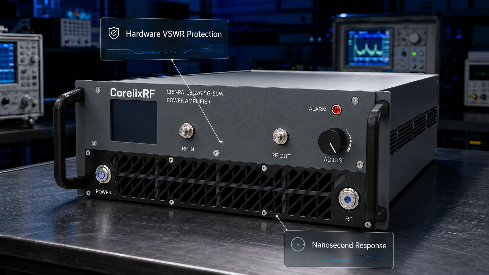
Primary engineering guide: this near-duplicate reference has been consolidated under How to Implement Hardware VSWR Protection in 8-12 GHz RF Systems?. Use the primary guide for the latest RF engineering review, compliance-safe wording, RFQ inputs and factory documentation path.
- Open the primary guide for the current topic cluster.
- Prepare RFQ inputs before requesting engineering review.
- Use the RF configurator to summarize band, power, interface and duty-cycle needs.
- Review delivery documentation for FAT-style evidence and shipment records.
- Contact CorelixRF when the project has a documented scope.
Archived page topic: How to Prevent GaN Amplifier Burnout Using Hardware VSWR Protection?. This page remains available for reference, but search engines are pointed to the primary guide through canonical consolidation.
Engineers often face catastrophic equipment failures when designing fast frequency hopping systems. Software-based polling delays create an unacceptable vulnerability during sudden antenna mismatch events. CorelixRF utilizes thirty years of manufacturing expertise, delivering a pure hardware-level analog protection architecture that physically prevents device destruction within nanoseconds.
The Hook: Anatomy of a Microsecond Catastrophe in Fast Frequency Hopping Systems
System integrators building electronic warfare payloads frequently encounter a terrifying scenario during field deployments. A tracked vehicle experiences immense mechanical vibration while traversing rough terrain. That extreme vibration shears a WR42 waveguide connection right off an active jamming array. Here’s the deal. Standard system architecture relies entirely upon software microcontrollers monitoring telemetry data. A master processor asks an analog-digital converter for reverse power readings every few milliseconds.
Radio frequency energy travels near light speed through transmission lines. When that physical break occurs, output energy hits an infinite impedance mismatch. Total reflection happens instantly. Fifty watts of K-band power bounces backwards toward your expensive Gallium Nitride output stage. Software routines require hundreds of clock cycles just for executing an interrupt request. Milliseconds pass before any digital shutdown command reaches that bias circuit. During those wasted milliseconds, reflected voltage waves combine continuously with forward waves. Drain voltage spikes massively beyond absolute maximum ratings. Transistor channels vaporize instantly. Your entire mission payload becomes dead weight because digital logic cannot outrun analog physics.
We observed this exact failure mode during three distinct client evaluations last quarter. First, an airborne radar pod lost its antenna radome at high altitude. Second, a shipborne tracking system suffered salt-fog corrosion which degraded connector mating surfaces. Third, an automated production test rack utilized faulty coaxial cables. In every single case, software logs indicated normal operation right up until complete module failure. Those logs proved digital telemetry polling remains too slow for fundamental hardware preservation.
Failure Timeline Breakdown
| Event | Time Elapsed | Digital State | Analog State |
| Waveguide Shears | 0 ns | Polling Loop Active | Infinite Mismatch |
| Reflection Hits Drain | 2 ns | Unaware | VSWR Exceeds 10:1 |
| Avalanche Breakdown | 50 ns | Unaware | Die Substrate Melts |
| ADC Samples Reverse Power | 500,000 ns | Reading Data | Amplifier Destroyed |
| MCU Issues Shutdown | 2,000,000 ns | Sending Command | Catastrophic Failure |
Mechanism Analysis: Why Software Polling Guarantees Failure in K-Band Applications
Microwave engineering demands profound respect for transmission line theory. Operating within an 18,000 – 26,500 MHz frequency range leaves zero margin for delayed reactions. What’s the real story? We must examine physical thermal time constants inherent within semiconductor structures. A high-power solid-state amplifier generates intense localized heat at microscopic gate junctions. When standing wave ratios degrade suddenly, efficiency drops drastically. RF energy previously radiating into space now dissipates entirely within transistor packages.
Many digital control designers fundamentally misunderstand how quickly thermal runaway occurs. They calculate average power dissipation instead of analyzing transient peak voltages. A software engineer might program a ten-millisecond delay before triggering an alarm, avoiding false positives caused by normal system jitter. That arbitrary software delay guarantees hardware destruction. K-band wavelengths measure roughly one centimeter. Any physical disconnection creates massive phase shifts rapidly. Peak voltages double across drain terminals, punching straight through depletion regions.
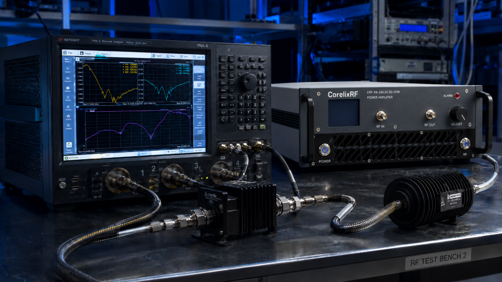
Consider a standard laboratory setup using vector network analyzers. Engineers sweep frequencies rapidly across wide bands. If test port cables loosen slightly, return loss measurements collapse instantly. An operator cannot react fast enough. A digital control loop behaves exactly like a slow human operator. It waits, observes, calculates, and acts much too late. Real engineering truth dictates that protective systems must operate faster than failure mechanisms. We cannot patch flawed physical architectures using clever code.
Thermal and Voltage Constants
| Parameter | Software Response | GaN Failure Threshold |
| Detection Speed | 1 – 10 Milliseconds | < 100 Nanoseconds |
| Over-voltage Duration | > 500 Microseconds | < 50 Nanoseconds |
| Thermal Overload | Averaged Over Time | Instantaneous Peak |
| Architecture Type | Serial Processing | Physical State Change |
| Reliability | Dependent on Code | Physics-Based |
Hardware Selection Traps in Agile Radar Architectures
Procurement teams frequently fall into dangerous traps when selecting components. They compare data sheets focusing purely on output power and price. You might be wondering. Why do cheap commercial modules fail so consistently during military-grade field trials? Cheap designs cut corners exactly where unseen problems hide. Budget manufacturers implement simple serial interfaces for all diagnostic functions. They feed forward and reverse detector voltages directly into slow microprocessors.
This cost-saving measure looks fine on paper. System integrators read “VSWR Protection” on promotional brochures and assume safety exists. True system reliability requires deep investigation into actual circuit topologies. You must ask vendors how their protection loop physically operates. If they mention firmware updates or microcontroller algorithms, walk away immediately. Fast frequency hopping systems change operating states faster than standard telemetry buses can update. A frequency hop might occur every ten microseconds. A localized mismatch at one specific frequency could reflect lethal power before your control software even registers a band change.
A defense contractor recently attempted integrating consumer-grade parts into drone countermeasure platforms. Their software developers spent weeks writing complex error-handling algorithms. During their first vibration test, three separate power modules burned out sequentially. They analyzed failed boards and discovered melted traces near output matching networks. Their entire software-centric design philosophy failed because they trusted marketing claims over rigorous hardware evaluation. Real solutions require dedicated analog comparator circuits acting independently from any digital processing layer.
Component Sourcing Evaluation
| Feature | Budget Module | Engineering Grade |
| VSWR Detection | ADC to MCU | High-Speed Analog Comparator |
| Shutdown Mechanism | Serial Bus Command | Direct Gate Bias Cutoff |
| Reaction Time | Milliseconds | Nanoseconds |
| Dependency | Firmware Stability | Hardware Physics |
| Field Reliability | Poor | Exceptional |
The CorelixRF Solution: Nanosecond Hardware-Level Analog Protection
CorelixRF designs equipment prioritizing fundamental physical reality over convenient software abstractions. Our facility produces solutions specifically targeting these exact integration nightmares. This is where it gets interesting. We bypass digital microcontrollers entirely during critical fault conditions. Our proprietary internal protection circuitry features direct analog hardware interlocking. A directional coupler continuously samples reverse power at the final output stage.
This sampled voltage feeds directly into an ultra-fast analog comparator. We hard-wire a physical threshold voltage representing absolute maximum safe return loss. When a broken antenna causes reverse power spikes, our comparator trips instantaneously. It triggers an electronic switch connected straight toward primary RF input stages and drain bias rails. The drive signal disappears within nanoseconds. Digital software can crash, freeze, or poll slowly without causing any harm. Our analog gatekeeper acts autonomously, preserving your expensive active components.
This unyielding approach defines our entire manufacturing philosophy. Four hundred dedicated staff members build hardware utilizing these uncompromising principles every single day. We understand what happens on tracking ships during heavy storms. We know how test racks behave when technicians accidentally disconnect live cables. Therefore, we embed genuine resilience deep inside our circuit boards. You simply cannot fake reliability through programming. You must build it using copper, silicon, and unshakeable analog design rules.
Analog Loop Characteristics
| Stage | Component | Action Time |
| Sensing | Directional Coupler | Speed of Light |
| Threshold | Analog Comparator | < 5 Nanoseconds |
| Actuation | High-Speed RF Switch | < 15 Nanoseconds |
| MCU Notification | RS485 Interface | 5 Milliseconds (Non-critical) |
| Total Protection | End-to-End | < 20 Nanoseconds |
CorelixRF CRF-PA-18000M26500M-50W GaN Amplifier Specifications
Let us examine specific parameters proving our objective capability. We built a wideband module operating specifically for demanding environments. Ready for the good part? The CorelixRF CRF-PA-18000M26500M-50W delivers a rated output power reaching 50 W. This unit provides exceptional gain performance measuring 50 dB. A critical metric for hopping systems remains gain flatness, which we strictly control between -5 and 5 dB across all frequencies.
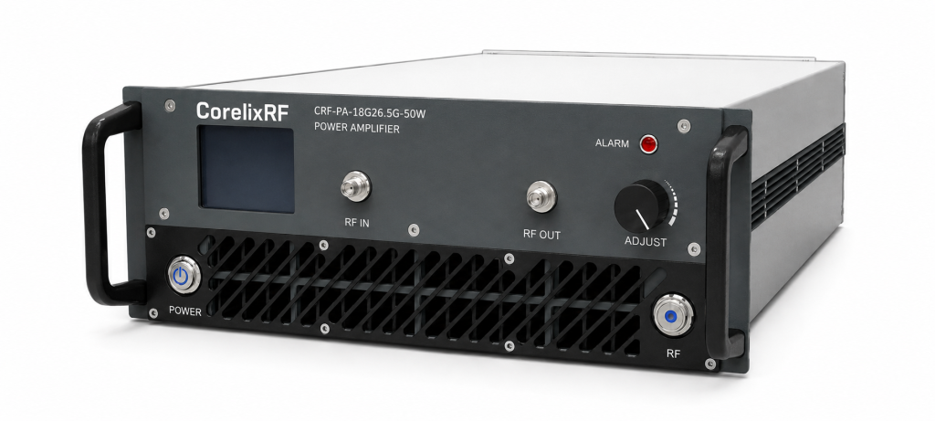
We base this design upon advanced GaN technology. Gallium Nitride provides necessary power density, but requires our stringent protection mechanisms. The datasheet explicitly lists built-in protection handling over-voltage, over-temperature, over-drive and VSWR conditions. Engineers connect input signals through a precision 2.92mm-Female connector. High-power output flows safely through a rugged WR42 waveguide interface. Power consumption stays manageable around 400 W.
Cooling methods utilize forced air cooling, keeping operating temperatures safely between 0 and 50 °C. We package everything into a standard 19″, 3U chassis weighing 14.5 kg. Control interfaces include RS485 / LAN connections for monitoring purposes. Harmonics stay suppressed down near -20 dBc, while spurious emissions drop below -60 dBc. These figures represent verified engineering reality, tested vigorously before shipping.
Electrical Specifications Table
| Parameter | Minimum | Typical | Maximum |
| Frequency Range | 18,000 MHz | – | 26,500 MHz | | Rated Output Power | 50 W | – | – | | Gain | 50 dB | – | – | | Power Consumption | – | 400 W | – | | Operating Temp | 0 °C | – | 50 °C |
Field Troubleshooting and Integration Best Practices
Integrating high-power modules requires methodical verification techniques. Never trust software interfaces blindly when powering up untested antenna arrays. Let’s examine the facts. An experienced engineer always verifies hardware protection mechanisms offline first. We recommend utilizing high-power attenuators and network analyzers for initial baseline measurements. Establish normal operating return loss figures before activating full drive power.
You must design system-level interlocks honoring physical delays. If your agile system commands a frequency jump, blank RF input signals momentarily. Allow synthesizer settling times before re-applying drive. Our hardware protects against catastrophic faults, but continuous intentional mismatching degrades long-term component lifespans. Treat fast VSWR protection like an automotive airbag. It saves lives during accidents, but you shouldn’t crash cars daily just for testing it.
Always measure actual power supply transient responses under heavy modulation. When an amplifier draws high current dynamically, voltage rail droop can trigger false alarms. Utilize high-bandwidth oscilloscopes monitoring drain voltage test points alongside forward RF power envelopes. This rigorous methodology separates competent system integrators from amateurs. Thorough physical verification eliminates mysterious field failures permanently.
Integration Verification Checklist
| Step | Verification Action | Expected Outcome |
| 1 | VNA Sweep Cold Antenna | VSWR < 1.5:1 |
| 2 | Small Signal Drive | Stable Gain Profile |
| 3 | Pulsed Power Test | Clean Envelope Edges |
| 4 | Induce Mild Mismatch | Forward Power Adjusts |
| 5 | Full Power Operation | Nominal Thermal Load |
Professional Conclusion
True system reliability demands hardware architectures respecting fundamental physical constraints rather than relying upon slow digital software routines. CorelixRF solves catastrophic mismatch failures through rigorous, high-speed analog engineering principles. Stop gambling your mission payloads on microcontroller polling loops. Contact our technical team today for comprehensive datasheets and structural integration guidance regarding your specific radar or electronic warfare requirements.
FAQ
Q1: What is the CRF-PA-18000M26500M-50W? The CRF-PA-18000M26500M-50W operates as a wideband RF power amplifier providing 50W output across an 18 to 26.5 GHz spectrum.
Q2: How does built-in VSWR protection work? Our system utilizes fast analog hardware comparators detecting reverse power instantly, bypassing digital software delays completely.
Q3: What applications suit this amplifier best? Engineers deploy this equipment primarily for test & measurement, communication, interference, and aviation control systems.
Q4: What are the physical dimensions and weight? This product ships in a standard 19-inch 3U rackmount package weighing exactly 14.5 kilograms.
Q5: What cooling method does this device require? We integrated a robust air cooling mechanism maintaining safe operating temperatures between 0 and 50 degrees Celsius.
Turn this RF requirement into a quotable specification
Use this article as a starting point for a buildable RF specification. Before quoting, CorelixRF normally checks frequency range, output power, gain flatness, duty cycle, load mismatch, thermal path, control interface, enclosure limits and acceptance data.
- VSWR protection articles – continue with related mismatch, reflected-power and protection design notes
- RF power amplifier platforms – match the article topic to available RF power amplifier families
- solid state power amplifier page – review SSPA architecture when reliability and repeatable test data matter
- RFQ checklist – send the data buyers usually forget, including band, power, duty cycle, interface and test standard
- delivery documentation – check what documents can support incoming inspection, FAT review and long-term maintenance
- case studies – review similar engineering paths before sending an RFQ
- engineering contact – send the application notes, block diagram or target specification to engineering sales
For a faster review, send operating band, power target, modulation or waveform, antenna/load condition, cooling limit, mechanical envelope and target test standard through the RFQ or contact path.