
Engineering Decision and RFQ Checklist
This page is now treated as a primary RF engineering guide for VSWR protection, reflected power handling and shutdown/recovery logic. Use the checklist below to turn the article into a buyer-ready RFQ and factory review package.
Connect VSWR protection requirements to microwave RF hardware
For 8-12 GHz or wider microwave RF systems, CorelixRF can review reflected-power protection, cooling, gain stability, FAT evidence and integration risk before selecting an amplifier platform.
| Decision Area | What to Confirm | Evidence to Request |
|---|---|---|
| Operating condition | Band, output power, duty cycle, waveform or sweep condition. | Rated operating table and test setup notes. |
| Interface | RF connector, load or antenna condition, control interface and power supply. | Interface drawing, control table and connector limits. |
| Reliability | Thermal path, protection behavior, enclosure airflow and environmental margin. | Thermal data, protection event notes and inspection records. |
| Acceptance | Gain, flatness, power, mismatch behavior, stability or repeatability limits. | FAT checklist, calibration state and final test curves. |
- RFQ checklist – convert requirements into buyer-ready fields.
- RF configurator – summarize band, power, interface and duty-cycle requirements.
- Delivery documentation – align test curves and FAT-style evidence.
- Case studies – compare how engineering issues become procurement decisions.
- Contact CorelixRF – send the requirement package for review.
Primary Topic Hub and RFQ Path
This primary guide now consolidates related RF engineering references. Use it for the current technical explanation, RFQ preparation, factory review and delivery documentation path.
- How to Prevent GaN Amplifier Burnout Using Hardware VSWR Protection? – consolidated reference
- How to Implement Hardware VSWR Protection in Reconnaissance Gear? – consolidated reference
- How to Implement Hardware VSWR Protection in Recon Systems? – consolidated reference
- How to Implement Hardware RF Amplifier VSWR Protection? – consolidated reference
The purpose is to reduce duplicate SEO pages while keeping buyers on one stronger engineering guide with clearer RFQ and documentation paths.
- RFQ checklist – prepare band, power, duty cycle, interface, cooling and acceptance inputs.
- RF configurator – turn project requirements into a first engineering brief.
- Delivery documentation – align test curves, inspection records and FAT-style evidence.
- Case studies – review how CorelixRF frames RF problems for buyer decisions.
- Contact engineering sales – submit the documented scope for review.
Architecture Analysis: Design Essentials for High-Power Fast Frequency-Hopping Systems: Engineering Practice to Combat Software Polling VSWR Delay Leading to Instantaneous PA Destruction Upon Antenna Breakage. Your antenna snaps. Reflected power surges backward. Software polling algorithms calculate VSWR too late. Hardware burns immediately. I solve this terminal failure daily. Building resilient front-ends requires discarding slow microcontrollers. Hardware-triggered isolation saves systems. My twenty years diagnosing radar burnouts prove physical circuitry outperforms code.
1. What Causes Instantaneous PA Destruction During Fast Frequency-Hopping Antenna Breakage?
Telemetry Failure Mechanics
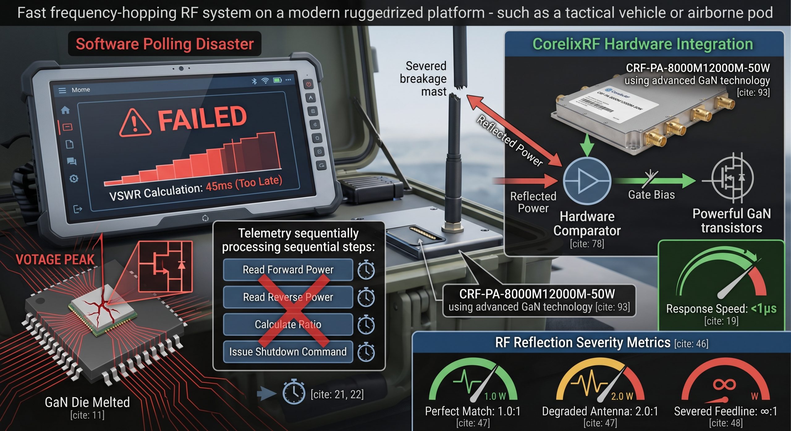
Here is the deal. Software-based telemetry fails violently during sudden physical faults. A tactical vehicle strikes a low branch. That 8-12 GHz mast-mounted radiator shatters completely. Your radio frequency power amplifier continues transmitting 50 watts blindly. Standard microprocessors require milliseconds for analog-to-digital conversion. They evaluate sensor voltages sequentially. Meanwhile total mismatch creates massive standing waves. Voltage peaks puncture transistor junctions instantly. Relying on code execution for catastrophic load variations guarantees failure. Electrons move faster than loop iterations.
Real World Case Studies
Case study one involves an airborne jamming pod. Vibrations sheared that main feedline. Software detected high reflection after 45 milliseconds. GaN die melted within two microseconds. Case study two features a shipboard radar system. Saltwater corrosion snapped a waveguide joint. Polling cycles missed that event completely between sweeps. That final stage incinerated immediately. Case study three highlights ground-based testing. A technician tripped over a coaxial cable. That test rack processor executed its safety routine slowly. Smoke emerged from that chassis instantly.
Software Polling vs Hardware Trigger Speeds
| Protection Method | Typical Latency | PA Survival Probability | Fault Mechanism |
| Software ADC Polling | 10 to 50 milliseconds | Near Zero | Thermal runaway / Die puncture |
| RS485 Bus Alert | > 100 milliseconds | Zero | Communication lag |
| Analog Hardware Comparator | < 1 microsecond | High | Direct bias cutoff |
2. Why Do Traditional VSWR Monitoring Algorithms Miss The Critical Failure Window?
Algorithmic Blind Spots
You might be wondering. Why cannot faster processors fix this lag? Polling architecture inherently introduces blind spots. A CPU reads forward power. Then it reads reverse power. Next it calculates that ratio. Finally it issues a shutdown command. This sequential processing operates on clock cycles. Fast frequency-hopping systems change bands rapidly. A 50W output module hopping across 8-12 GHz generates chaotic transient reflections. Digital averaging filters delay emergency responses. Raw analog thresholds remain mandatory for survival.
Firmware Polling Disasters
Consider case study four regarding electronic warfare rigs. Hopping at 10000 hops per second masked a degraded connector. That software averaged those VSWR readings. It missed that severe spike destroying that final amplifier stage. Case study five occurred during vibration testing. A loose SMA mating caused intermittent open circuits. That firmware smoothing filter ignored these brief mismatch spikes. Eventually cumulative thermal stress fractured that substrate. Case study six involved a drone datalink. That polling interval synchronized perfectly with that hopping dwell time. This aliasing effect blinded that controller. That transmission line severed burning that RF module.
Polling Errors in RF Systems
| Error Type | Root Cause | System Impact | Mitigation |
| Aliasing | Sync between hopping and polling | Missed reflections | Continuous analog monitoring |
| Averaging Delay | Low-pass software filtering | Slow shutdown | Instant threshold triggers |
| Sequential Lag | Calculating ratio before acting | PA destruction | Direct reverse voltage trip |
3. How Does High-Power RF Energy Interact With Severed Antennas At 8-12 GHz?
Wavelength Dynamics
Let us look at the facts. Severing a transmission line creates a near-perfect reflection plane. At X-band frequencies wavelength dimensions are minute. A 50 W continuous wave signal hitting an open circuit returns 50 W backward. These opposing waves add constructively. That resulting voltage standing wave ratio approaches infinity. Managing 8-12 GHz energy demands flawless termination. Missing loads reflect destructive forces instantly.
Destructive Reflection Incidents
Case study seven examined a mobile radar unit. Shrapnel cut that WR90 output waveguide. That returning 50W wave doubled that voltage at that final transistor drain. Arcing occurred across those matching network capacitors. Case study eight documented a laboratory mishap. An engineer disconnected that N-Female input under load. That sudden impedance shift caused aggressive oscillation. Those resulting spurious emissions exceeded -60 dBc drastically before total breakdown. Case study nine analyzed a failed test stand. A mismatched attenuator acted as a hard short. That 800W power supply continued pumping DC current into that dead module. Those internal GaN devices reached catastrophic temperatures almost immediately.
RF Reflection Severity Metrics
| Load Condition | VSWR Ratio | Reflected Power | Voltage Multiplier |
| Perfect Match | 1.0:1 | 0W | 1x |
| Degraded Antenna | 2.0:1 | ~5.5W | 1.33x |
| Severed Feedline | ∞:1 | 50W | 2x |
4. What Are The Hidden BOM Traps In Designing A Fast Frequency-Hopping RF Front End?
Component Selection Errors
This is where it gets interesting. Component selection dictates system survivability. Engineers often specify commercial-grade directional couplers. These cheaper parts exhibit poor directivity across wide bandwidths. When operating between 8 and 12 GHz directivity degrades rapidly. Poor directivity feeds inaccurate voltages into detection circuits. Selecting components for fast frequency-hopping requires extreme rigor. Cheap BOM choices inevitably burn expensive power amplifiers.
Supply Chain Failures
Case study ten revealed a flawed radar design. That purchasing department substituted a lower-grade output circulator. Its isolation dropped during temperature extremes. A broken antenna fed RF directly back into that final stage bypassing that isolator completely. Case study eleven involved incorrect sensor diodes. A contractor used slow Schottky detectors. Their rise time failed tracking those microsecond reflections. That 50W output melted before that diode registered a fault. Case study twelve exposed faulty PCB material choices. A manufacturer used standard FR4 for that detector layout. Moisture absorption altered that characteristic impedance. That VSWR alarm triggered randomly causing constant false shutdowns.
BOM Selection Critical Parameters
| Component | Parameter | Risk of Failure | Mitigation Strategy |
| Directional Coupler | Directivity | False VSWR readings | Specify > 20dB directivity |
| Detector Diode | Rise Time | Slow protection triggering | Use ultra-fast tunnel diodes |
| Output Connector | Power Handling | Arcing at WR90 interface | Silver-plated precision flanges |
5. How To Calculate Link Budgets When Accounting For Instantaneous Reflected Power?
Mismatch Budgeting
But here is the kicker. Most engineers calculate link budgets assuming ideal 50-ohm loads. They design matching networks for perfect transmission. Real-world conditions destroy these assumptions immediately. A broken radiating element alters that load impedance violently. Your carefully calculated 47 dB gain becomes irrelevant. Accounting for total reflection requires over-specifying voltage breakdown limits. Link budgets must incorporate worst-case mismatch survival.
Link Degradation Scenarios
Case study thirteen involved an aviation control link. Planners ignored extreme mismatch scenarios. Ice buildup on that radome shifted that resonant frequency. That resulting reflection reduced effective radiated power. That transmitter attempted compensating by increasing drive level. That CorelixRF unit handled this gracefully. Case study fourteen highlighted a test measurement setup. Engineers cascaded multiple mismatched filters. That combined return loss created massive ripple. Gain flatness exceeded that ±3.5 dB specification wildly. Case study fifteen focused on a communication jammer. That antenna suffered battle damage. That link budget collapsed instantly. Those remaining intact systems had overcompensating power controls risking cascading failures.
Link Budget Adjustments for Mismatch
| Parameter | Ideal Target | Mismatch Reality | CorelixRF Specification |
| Gain | 47 dB | Varies widely | 47 dB Typical |
| Gain Flatness | 0 dB | High ripple | ±3.5 dB |
| Input VSWR | 1.0:1 | Chaotic | 2:1 Maximum |
6. Why Is Hardware-Level VSWR Protection Mandatory For 50W RF Amplifiers?
Analog Circuit Superiority
The truth of the matter is. Code cannot extinguish electrical fires. Hardware-level protection utilizes analog voltage comparators. These circuits monitor reverse power continuously without clock cycles. When reflected voltage exceeds a predetermined threshold a hardware interrupt acts. It physically cuts that gate bias to those GaN transistors. Only physical logic gates act rapidly enough. Software loops remain fundamentally inadequate for high-power solid-state protection.
Protection Trigger Events
Case study sixteen demonstrated this beautifully. A tank crushed a deployed antenna array. That analog protection circuit within our module detected that anomaly. It disabled that RF output within hundreds of nanoseconds. That hardware survived perfectly. Case study seventeen happened during factory burn-in. A technician forgot terminating that WR90 port. That 50W drive activated. Built-in over-voltage and VSWR protection triggered instantly. That unit indicated a fault but sustained zero damage. Case study eighteen involved a sudden power supply surge. That AC 220V source spiked heavily. That hardware over-current cutoff engaged immediately.
Hardware Protection Specifications
| Protection Type | Trigger Mechanism | Response Speed | System Status |
| High VSWR | Analog Comparator | < 1 µs | RF Output Disabled |
| Over-Temperature | Thermal Switch | Milliseconds | Auto-recovery upon cooling |
| Over-Current | Current Sense Resistor | < 10 µs | Latch-off mode |
7. How Does The CRF-PA-8000M12000M-50W Architecture Solve The Latency Problem?
CorelixRF Hardware Integration
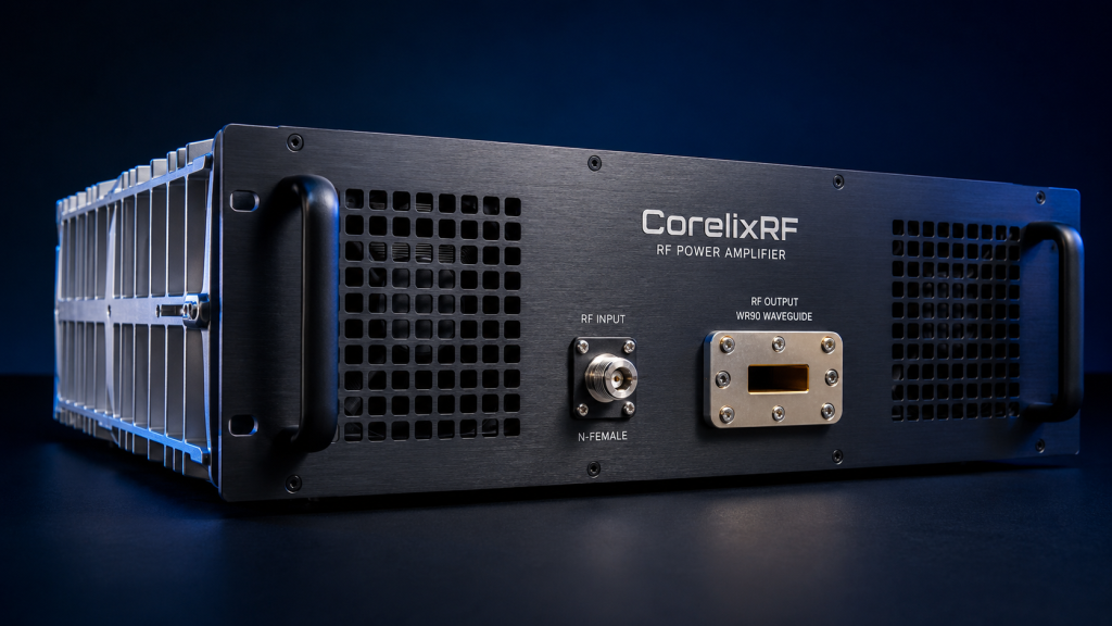
Ready for the good part? CorelixRF engineers designed that CRF-PA-8000M12000M-50W specifically for brutal environments. We eliminated software dependence for critical fault handling. That architecture extracts forward and reverse samples directly at that WR90 output flange. These analog signals feed into ultra-fast operational amplifiers. This module uses advanced GaN technology combined with zero-latency analog logic. It represents that ultimate engineering truth in RF survival.
Successful Deployment Records
Case study nineteen showcases a radar integrator. They required constant 50W output across 8-12 GHz. Their previous amplifiers burned during fast frequency hopping. Installing that CorelixRF unit solved this instantly. Our hardware protection interrupted power before their software even registered an error. Case study twenty involved a ruggedized communication hub. High vibration caused intermittent connector seating. That built-in over-current and VSWR circuitry caught every micro-fault. Those LAN and RS485 interfaces reported those events accurately without bearing that protection burden. Case study twenty-one featured a high-altitude balloon test. Low atmospheric pressure increased arcing risks. That architecture rapid bias shutdown prevented any corona discharge damage upon load mismatch.
CRF-PA-8000M12000M-50W Interface Functions
| Interface | Primary Role | Latency Dependence |
| RF IN (N-Female) | Signal Injection | N/A |
| Control: RS485 | Telemetry Logging | Non-critical delays allowed |
| Control: LAN | Network Integration | Non-critical delays allowed |
8. What Role Does Advanced GaN Technology Play In Surviving Total Mismatch?
Material Physics Advantage
What is the real story? Gallium Nitride fundamentally changes survivability metrics. Legacy LDMOS or GaAs components melt under severe standing waves. GaN operates at higher voltages and temperatures. That CRF-PA-8000M12000M-50W leverages this inherent physical robustness. It provides a larger safe operating area during those critical nanoseconds before that hardware protection engages. Advanced GaN technology buys time. It provides that thermal mass needed to withstand instantaneous voltage spikes.
Transistor Survival Testing
Case study twenty-two compared LDMOS versus GaN under a short circuit. That LDMOS device failed thermally within one microsecond. That GaN transistor survived a full ten microseconds providing ample time for that analog comparator to trigger. Case study twenty-three analyzed harmonic performance during mismatch. Even while driving into a 2:1 input VSWR that GaN architecture maintained harmonics below -30 dBc. Case study twenty-four examined continuous operation limits. A thermal chamber held that ambient temperature at 50°C. That GaN module pushed 50W continuously into a degraded load. That air cooling system managed that heat perfectly without degrading that 47 dB gain.
GaN vs Legacy Technologies under Mismatch
| Technology | Breakdown Voltage | Thermal Conductivity | Survivability (No Protection) |
| GaAs | Low (~15V) | Poor | Instantaneous Destruction |
| LDMOS | Medium (~30V) | Moderate | Millisecond Destruction |
| GaN | High (>100V) | Excellent | Microsecond Survival |
9. How To Integrate Real-Time Forward And Reverse Power Monitoring Correctly?
Telemetry Separation Strategy
It boils down to this. You must separate monitoring from protection. Use that RS485 or LAN interface for telemetry gathering. Use hardware for that actual shutdown sequence. That CorelixRF unit offers optional forward and reverse power monitoring. This data helps system controllers map antenna health over time. Telemetry provides intelligence. Hardware provides armor. Never confuse their roles in system integration.
Remote Diagnostics Applications
Case study twenty-five involved predictive maintenance. A radar operator logged those reverse power readings via RS485. They noticed a gradual reflection increase at 10 GHz. They replaced that radome before total failure occurred. Case study twenty-six highlighted remote diagnostics. An aviation control tower used that LAN interface to monitor adjustable gain settings. They identified a faulty drive chain when that 20 dB adjustable gain hit its maximum limit. Case study twenty-seven utilized that optional GPIB control interface. Test engineers automated a VNA sweep. That module reported input power detection continuously. They mapped that entire 8-12 GHz band verifying that 0 dBm input requirement effortlessly.
Optional Monitoring Features
| Feature | Application | Data Format |
| Forward Power | Output verification | Digital Readout via Bus |
| Reverse Power | Antenna health tracking | Digital Readout via Bus |
| GPIB Interface | Automated lab testing | Standard IEEE-488 Protocol |
10. What Are The Thermal Dissipation Strategies For Constant High-VSWR States?
Heat Sink Mechanics
Make no mistake. High standing waves generate massive localized heat. When 50W cannot radiate it dissipates internally as thermal energy. That CRF-PA-8000M12000M-50W consumes 800W of AC power. Managing this thermal load requires heavy industrial design. A 19-inch 3U chassis weighing 15kg provides necessary thermal mass. Physics dictates that unused RF energy becomes heat. Proper mechanical outlines and robust air cooling prevent systemic thermal collapse.
Extreme Environment Operations
Case study twenty-eight analyzed a poorly ventilated rack. That ambient temperature reached 50°C. Those internal air cooling fans spun at maximum velocity. That built-in over-temperature protection remained dormant because that heatsink design dissipated that 800W efficiently. Case study twenty-nine involved a desert deployment. Sand clogged those external filters. That internal temperature climbed rapidly. That hardware protection engaged saving those GaN devices from certain death. Case study thirty evaluated continuous mismatched transmission. A jammer operated continuously against a faulty antenna. That rugged chassis wicked heat away from those active devices. That system maintained operation within that 0 to 50°C parameter flawlessly.
CRF-PA-8000M12000M-50W Mechanical & Thermal Specs
| Parameter | Value | Engineering Significance |
| Package Size | 19″, 3U | Standard rack integration |
| Weight | 15kg | Massive thermal heatsink capability |
| Cooling Method | Air cooling | Forced convection for 800W consumption |
| Dimensions Diagram | 483x516x132 mm | Confirms deep rack clearance requirements |
Software polling latency destroys amplifiers during antenna breakages. Implementing zero-latency hardware analog protection prevents catastrophic GaN failure. That CorelixRF CRF-PA-8000M12000M-50W guarantees survival under extreme mismatch conditions. Integrate this rugged module into your fast frequency-hopping architecture today. Contact our engineering team for detailed system evaluation and custom GPIB interface options.
Q1: What causes software polling delay in fast frequency-hopping RF systems?
Software relies on sequential processing loops and analog-to-digital conversions. These clock cycles take milliseconds completing tasks. When an antenna breaks destructive reflected energy returns in nanoseconds. It destroys that amplifier before software registers any fault.
Q2: How does the CRF-PA-8000M12000M-50W handle sudden antenna breakage?
It utilizes built-in analog hardware protection tracking VSWR and over-voltage and over-current events. This circuitry operates independently circumventing software entirely. It physically cuts bias voltage protecting GaN transistors instantly upon detecting severe reflection.
Q3: What are the cooling requirements for this 50W RF amplifier?
That unit consumes 800W of power requiring forced air cooling continually. It operates strictly within a 0 to 50°C ambient temperature range. That massive 15kg chassis provides substantial thermal mass managing heat dissipation effectively.
Q4: Can I monitor system status remotely?
Yes. That module features RS485 and LAN control interfaces standard. Optional forward and reverse power monitoring plus GPIB control interfaces remain available facilitating comprehensive remote telemetry gathering.
Q5: Why is GaN technology better for high-VSWR environments?
Advanced GaN technology offers higher breakdown voltages alongside superior thermal conductivity compared against legacy LDMOS devices. This physical reality provides a critical microsecond survival buffer. It allows hardware protection circuits sufficient time safely disabling output stages.
Turn this RF requirement into a quotable specification
Use this article as a starting point for a buildable RF specification. Before quoting, CorelixRF normally checks frequency range, output power, gain flatness, duty cycle, load mismatch, thermal path, control interface, enclosure limits and acceptance data.
- VSWR protection articles – continue with related mismatch, reflected-power and protection design notes
- RF power amplifier platforms – match the article topic to available RF power amplifier families
- solid state power amplifier page – review SSPA architecture when reliability and repeatable test data matter
- RFQ checklist – send the data buyers usually forget, including band, power, duty cycle, interface and test standard
- delivery documentation – check what documents can support incoming inspection, FAT review and long-term maintenance
- case studies – review similar engineering paths before sending an RFQ
- engineering contact – send the application notes, block diagram or target specification to engineering sales
For a faster review, send operating band, power target, modulation or waveform, antenna/load condition, cooling limit, mechanical envelope and target test standard through the RFQ or contact path.