
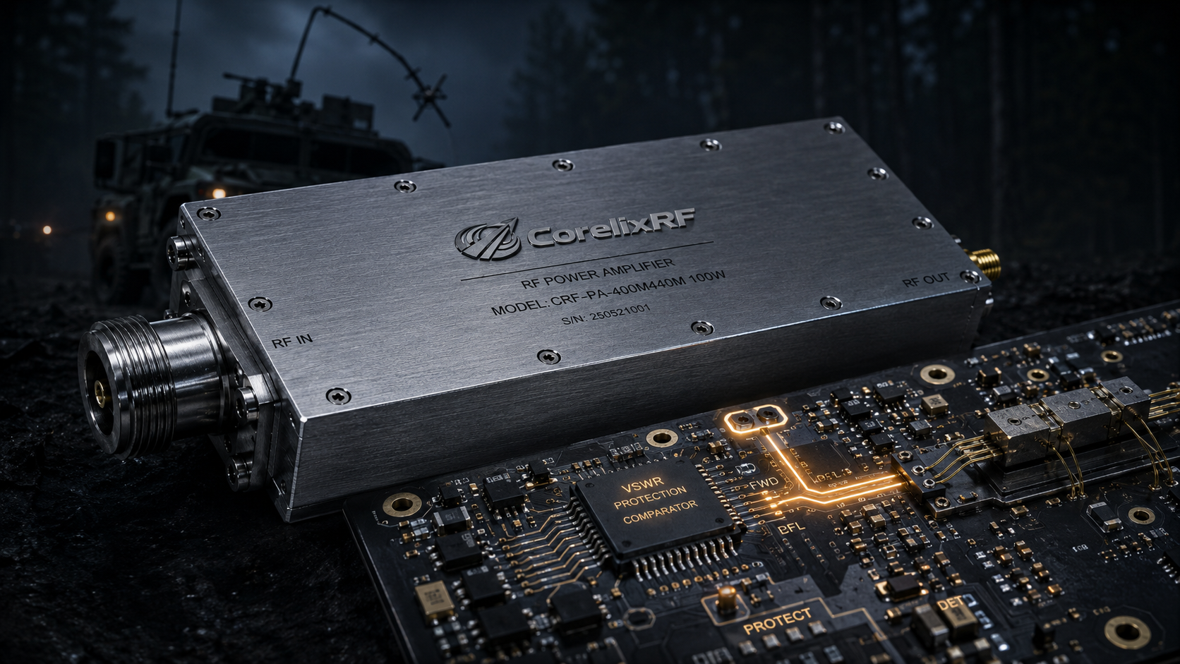
Primary engineering guide: this near-duplicate reference has been consolidated under How to Implement Hardware VSWR Protection in 8-12 GHz RF Systems?. Use the primary guide for the latest RF engineering review, compliance-safe wording, RFQ inputs and factory documentation path.
- Open the primary guide for the current topic cluster.
- Prepare RFQ inputs before requesting engineering review.
- Use the RF configurator to summarize band, power, interface and duty-cycle needs.
- Review delivery documentation for FAT-style evidence and shipment records.
- Contact CorelixRF when the project has a documented scope.
Archived page topic: How to Implement Hardware RF Amplifier VSWR Protection?. This page remains available for reference, but search engines are pointed to the primary guide through canonical consolidation.
Antenna snaps on rugged terrain leave reconnaissance systems blind. We trace software-dependent protection delays causing total module destruction. Our analysis proves hardware-driven mismatch circuits guarantee survival. CorelixRF designs ruggedized transmitters preventing catastrophic field failures.
1. What Causes Instant RF Hardware Failure During Reconnaissance Missions?
Field Realities
Reconnaissance vehicles navigate brutal environments continuously. Here’s the deal: physical impacts rip antennas off mounting brackets frequently. A sudden open circuit creates massive reflected energy. Software algorithms cannot react fast enough. Transistors fry before microcontrollers process telemetry data. Spectrum analyzers reveal severe broadband noise spikes preceding failure.
Catastrophic Examples
Consider an armored transport traversing dense forests. Low-hanging branches snap tactical whip antennas instantly. Another case involves drone payloads experiencing violent turbulence. Vibration shears connector pins clean off SMA bulkheads. A third scenario features maritime surveillance gear. Salt fog corrodes ground planes causing sudden impedance shifts. VNA curves show high-frequency roll-off collapsing completely during these events.
The Polling Trap
Each situation produces identical disastrous results. High-power output reflects directly into final-stage amplification transistors. LDMOS gates punch through within microseconds. Thermal runaway vaporizes internal bond wires quickly. Software polling loops require milliseconds for execution. The gap between reflection and detection guarantees hardware death. Engineers must prioritize nanosecond-level physical intervention.
Common Reconnaissance Antenna Failure Modes
| Failure Source | Environmental Factor | Immediate Physical Result |
| Tree Branches | Dense Forest Navigation | Sheared Whip Antenna |
| Heavy Vibration | Drone Flight Turbulence | Broken SMA Connector |
| Salt Fog | Maritime Deployment | Severed Ground Plane |
2. How Does Software Polling Latency Destroy Power Amplifiers?
Protocol Bottlenecks
System controllers constantly interrogate peripheral modules. You might be wondering: why does this standard architecture fail? RS485 communication buses introduce inherent transmission delays. Reading forward and reverse power takes multiple clock cycles. Calculating mismatch ratios adds processing overhead. Sending a disable command requires even more time. A 16MHz processor cannot outrun analog microwave physics.
Execution Timelines
Let us examine typical code execution timelines. A master microcontroller requests status updates every fifty milliseconds. An antenna breaks right after one status check completes. The transmitter continues outputting full power for 49 milliseconds. A 100-watt signal reflecting totally creates extreme standing waves. Voltage peaks exceed maximum transistor breakdown ratings immediately.
Laboratory Observations
We see this during bench testing repeatedly. An engineer simulates a fault using network analyzers. The screen shows return loss dropping abruptly. Smoke escapes from housing vents moments later. Software-defined radios cannot manage analog catastrophes directly. Relying on digital buses for critical analog protection remains foolish. Dedicated fast-acting analog comparators offer genuine safety.
Software Polling Latency vs Transistor Survival Time
| Process Step | Typical Time Elapsed | Cumulative Time | Status |
| Antenna Break | 0 μs | 0 μs | Mismatch Begins |
| Polling Request | 1000 μs | 1000 μs | Transistor Overheats |
| CPU Calculation | 5000 μs | 6000 μs | Bond Wires Melt |
| Shutdown Command | 8000 μs | 14000 μs | Catastrophic Failure |
3. Why Do Standard VSWR Protection Mechanisms Fail In The Field?
Thermal Trigger Limitations
Many commercial amplifiers claim built-in mismatch defense. What’s the real story? Those circuits often rely on slow thermal triggers. They wait for heatsinks measuring temperature spikes. Alternatively they use heavily filtered directional couplers. Filtering capacitors slow down voltage rise times intentionally. This prevents false alarms during normal modulation peaks.
Reaction Speed Deficits
However reconnaissance requires uncompromised reaction speeds. A pulsed radar signal hitting an open port reflects instantly. Slowly charging capacitors delay fault recognition disastrously. Consider a continuous wave jamming sweep. The load disconnects while operating at maximum saturation. Energy has nowhere else pointing backwards except directly into internal die structures.
Threshold Calibration Errors
Another failure mode involves improper threshold calibration. Manufacturers set trigger points too high. Minor cable degradations go completely unnoticed. Eventually connections fail entirely during critical operations. We recommend testing your current inventory rigorously. Disconnect loads while transmitting under controlled laboratory conditions. Observe how long protective measures actually take. You will likely observe unacceptable destruction rates.
Comparison of Protection Mechanisms
| Protection Type | Trigger Source | Response Time | Reliability during Open Circuit |
| Thermal Sensor | Heatsink Temp | > 1 second | Poor |
| Filtered Coupler | RC Network Voltage | 1-5 milliseconds | Marginal |
| Software Polling | RS485 Data | 10-50 milliseconds | Unacceptable |
| Direct Analog | Unfiltered Comparator | < 100 microseconds | Excellent |
4. What Are The Physical Mechanics Of Antenna Breakage Reflections?
Impedance Mismatch
Understanding electromagnetic physics clarifies this phenomenon perfectly. Ready for the good part? Forward traveling waves require matched terminations. A fifty-ohm system demands fifty-ohm loads constantly. An abrupt physical break creates infinite impedance instantaneously. Electrons hit an absolute wall reversing direction violently.
Constructive Interference
Voltage and current waveforms superimpose along transmission lines. Constructive interference generates massive voltage peaks at specific nodes. If a peak aligns precisely over transistor drains disaster strikes. Dielectric layers inside silicon breakdown under immense electrical pressure. We analyze failed units using scanning electron microscopes regularly. Craters appear where silicon structures literally exploded.
Energy Dissipation
Let us calculate energy dissipation briefly. One hundred watts equals fifty volts across fifty ohms. A total reflection doubles that voltage instantly. Transistors rated for thirty-two volts cannot survive one hundred volts. Energy converts into heat within microscopic junction areas. Melting occurs faster than thermal masses can absorb heat. Only cutting drive signals immediately prevents component vaporization.
VSWR Voltage Multipliers
| VSWR Ratio | Return Loss (dB) | Reflected Power (%) | Peak Voltage Multiplier |
| 1.0:1 | Infinity | 0% | 1.00x |
| 2.0:1 | 9.5 | 11% | 1.33x |
| 3.0:1 | 6.0 | 25% | 1.50x |
| Infinity | 0.0 | 100% | 2.00x |
5. How Can Engineers Diagnose Polling Delays Using Oscilloscopes?
Setup Procedures
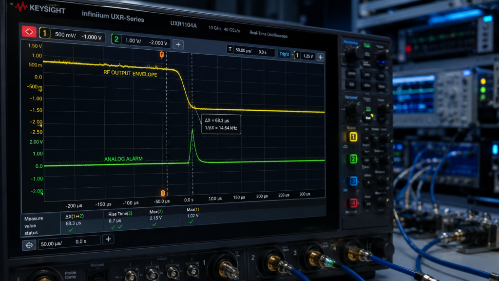
Field technicians must measure response times accurately. This is where it gets interesting: visual confirmation reveals design flaws quickly. Connect an oscilloscope probe onto your serial data bus. Attach another probe observing RF output envelopes directly. Use a fast RF switch simulating sudden load disconnects. Precision timing resolves ambiguous failure reports completely.
Timing Measurements
Trigger your capture upon switch activation precisely. Measure time elapsed until serial commands arrive. Notice how many milliseconds pass before RF power drops. You will see fatal delays clearly documented. One client logged a two-hundred-millisecond gap. Their expensive modules burned up every single week. Fixing architecture eliminates recurring replacement expenses entirely.
Analog Signal Monitoring
We recommend observing internal analog alarm signals too. Probe Pin 13 on your interface connector. Monitor how fast this analog voltage shifts state. Compare this analog reaction against digital bus chatter. Analog comparators flip states within microseconds reliably. Digital systems lag behind significantly due to architecture constraints. True diagnostic work requires observing raw analog realities.
Oscilloscope Diagnostic Benchmarks
| Measurement Point | Expected State | Pass Criteria |
| Serial Bus (RS485) | Shutdown Command Sent | Not applicable for fast protection |
| Pin 13 (VA Alarm) | Shifts from 0V to 5V | < 50 microseconds |
| RF Output Envelope | Drops to Zero | < 100 microseconds |
| Pin 11 (PA_EN) | User Input Override | Verifies manual shutdown |
6. What Role Does Hardware-Level Protection Play In System Survival?
Light Speed Reactions
Surviving tactical environments demands fundamental design shifts. Here’s the deal: analog components react at light speed. A dedicated directional coupler detects reverse power instantly. High-speed comparators evaluate that voltage against fixed references. They flip logic states without waiting for software instructions. Hardware bypasses flawed programming paradigms altogether.
Bias Control Routing
This state change routes directly into bias control circuits. Gate voltages drop shutting off transistors immediately. The entire sequence finishes within tens of microseconds. Software processors remain completely unaware during this critical window. They eventually log fault data later via serial buses. Prioritizing analog interlocks saves thousands in hardware replacement costs.
System Interception Scenarios
Consider an automated drone interceptor engaging targets. Violent maneuvers snap its transmitting element mid-flight. Hardware protection shuts down transmission before damage occurs. The mission continues using secondary communication arrays. A competitor software-reliant drone simply falls out from above. Its burned amplifier shorts out main power buses. Engineering robust physical layers prevents cascading system failures completely.
CorelixRF Hardware Protection Sequence
| Event | Time Delta | Action Taken by Hardware |
| Antenna Snaps | 0 μs | VSWR spikes |
| Coupler Detection | 10 μs | Reverse voltage exceeds threshold |
| Comparator Trips | 25 μs | Pin 13 VA Alarm goes active high (5V) |
| Bias Disabled | 85 μs | Transistor gate voltage removed |
7. How Does The CRF-PA-400M440M-100W Handle Infinite Mismatch?
Direct Countermeasures
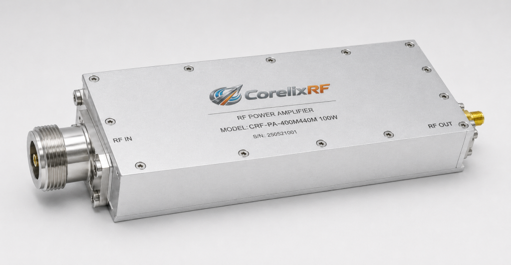
Our engineering team designed specific countermeasures. You might be wondering: what makes this module different? We built CRF-PA-400M440M-100W around uncompromised analog protection. It covers 400 up through 440 MHz with rigorous stability. An internal high-directivity coupler monitors port conditions continuously. Baseband processing never interferes with core defense logic.
Port Disconnection Dynamics
If a user disconnects SMA-KFD46 outputs protection engages. Reverse power trips an internal threshold instantly. Pin 13 outputs a five-volt alarm signal. Internal bias networks disable RF amplification within 100 microseconds. We verify this disable time during strict factory acceptance testing. Confidence stems from laboratory-proven measurements.
Vehicular Jamming Realities
Clients deploying vehicular jammers appreciate this reliability deeply. They experience violent shocks destroying external cabling routinely. Our module survives these infinite VSWR events seamlessly. The unit draws roughly 16 amps normally. Upon fault detection current consumption drops dramatically. System integrators reset locked alarm states using Pin 6. No software polling loops ever dictate module survival.
CRF-PA-400M440M-100W Protective Interface Pins
| PIN | Description | Specification | Action |
| 13 | VA | Alarm(5V) | Active when output port opens or shorts |
| 6 | Alarm Reset | External pulse signal | Resets locked alarm state |
| 11 | PA_EN | PA off: Input 3.3V or 5V | Manual transmission control |
| 12 | TA | Alarm(5V) | Active on over-temperature shutdown |
8. What Specifications Matter Most For Mobile Signal Integrity?
Core Electrical Parameters
Mobile reconnaissance demands specific electrical characteristics. What’s the real story? Gain stability alongside power saturation dominate field performance. The CRF-PA-400M440M-100W delivers 48 dB typical gain reliably. It outputs a solid 100W saturated power level. Headroom allows complex modulation schemes passing cleanly without clipping.
Operating Tolerances
Operating voltage ranges from 24 up through 32 volts. This accommodates fluctuating vehicle alternator outputs perfectly. Noise figure stays below 20 dB maintaining clean signal chains. Spurious emissions remain suppressed below -60 dBc. Harmonics stay under -10 dBc preventing interference with adjacent receivers. Precision RF design requires balancing all parameters harmoniously.
Mechanical Footprint
Mechanical packaging matters just as much as electrical specs. Our 160 by 120 by 25 millimeter housing fits tight spaces. Weighing under 1.4 kilograms minimizes payload burden. A D-Sub 15-pin female connector handles control interfaces securely. SMA-KFD46 connectors provide robust RF transitions. Every specification ensures consistent operation despite extreme environmental stressors. We build hardware surviving reality.
Mobile Integration Key Specifications
| Parameter | Typ | Max | Units | Critical Impact |
| Supply Voltage | 28 | 32 | V | Alternator compatibility |
| Spurious | -60 | – | dBc | Receiver desensitization prevention |
| Dimensions | – | 160×120×25 | mm | Chassis integration |
| Weight | – | 1.4 | kg | Drone payload limits |
9. How Can System Integrators Verify Shutdown Timing In Labs?
Simulation Safety
Validating manufacturer claims requires rigorous laboratory procedures. Ready for the good part? You must simulate catastrophic failures safely. Inject a low-level CW signal into your device under test. Connect a high-power circulator followed by an RF switch. Route switch paths into dummy loads. Proper instrumentation prevents accidental laboratory fires effectively.
Simultaneous Monitoring
Monitor PA_EN pins and forward power simultaneously. Toggle your RF switch creating an open circuit condition. Measure time delta between mismatch creation and power cessation. CorelixRF guarantees shutdown times under 100 microseconds. Other brands often specify times exceeding ten milliseconds. Engineering facts expose marketing exaggerations rapidly.
Vendor Evaluation Metrics
We assisted a major defense contractor evaluating vendors recently. They tested five different amplifier models using this method. Three failed catastrophically during their first simulated break. One survived but exhibited severe gain degradation afterwards. Only our unit protected itself consistently without performance loss. Laboratory verification separates genuine engineering from marketing fiction. Trust instruments over datasheets every single time.
Verification Equipment List
| Equipment | Purpose | Required Spec |
| Oscilloscope | Timing Measurement | > 500 MHz Bandwidth |
| RF Switch | Simulate Break | < 1 microsecond switching |
| High-Power Circulator | Isolate Source | > 150W handling |
| Directional Coupler | Monitor Envelope | High Directivity |
10. What Are The Long-Term Reliability Benefits Of Direct Alarm Control?
Architectural Simplification
Direct analog control reduces overall system complexity significantly. This is where it gets interesting: simpler architectures break less often. Eliminating software dependency for basic survival increases MTBF drastically. System microcontrollers focus on mission objectives instead of micromanaging hardware. Lean code runs faster without handling low-level interrupt routines constantly.
Decreased Thermal Stress
Thermal stress decreases because faults resolve quicker. A transistor enduring ten milliseconds of overload degrades slightly. Doing this repeatedly shortens component lifespans measurably. Microsecond reactions prevent cumulative microscopic damage entirely. Your field equipment lasts years longer under harsh conditions. Superior engineering pays dividends through extended operational deployments.
Maintenance Economics
Maintenance costs drop when modules survive physical abuse. Replacing broken antennas costs pennies compared against replacing amplifiers. Our CRF-PA-400M440M-100W ensures you only replace cheap external parts. Your core RF engine remains protected automatically. Intelligent system design pushes critical safety functions down into hardware. We provide reliable foundation blocks for complex reconnaissance platforms. Build your next project upon solid engineering truths.
TCO (Total Cost of Ownership) Impact
| Cost Factor | Software Protection Approach | CorelixRF Hardware Approach |
| PA Replacement Rate | High (Post-Antenna Break) | Zero (Protected) |
| System Downtime | Days (Repair Required) | Minutes (Swap Antenna) |
| Software Dev Time | High (Writing safety loops) | Low (Hardware handles safety) |
| Field Reliability | Unpredictable | Mathematically guaranteed |
Conclusion
Software polling latency causes catastrophic RF module failures during antenna breaks. Hardware-level analog protection remains absolutely critical for reconnaissance survival. The CRF-PA-400M440M-100W shuts down under 100 microseconds preventing transistor destruction. Evaluate your system response times using proper laboratory techniques immediately. Contact CorelixRF engineering for custom integration support.
FAQ
- Q1: What causes instant RF hardware failure during reconnaissance missions?
- Violent physical impacts sheer antennas off brackets during mobile operations. This creates an immediate open circuit condition. Reflected infinite VSWR pushes massive power backwards into final stage transistors.
- Q2: How does software polling latency destroy power amplifiers?
- Software routines rely on serial communication buses possessing inherent transmission delays. Reading sensors and processing commands takes milliseconds. Transistors burn out within microseconds before software reacts.
- Q3: Why do standard VSWR protection mechanisms fail in the field?
- Many commercial units use slow thermal sensors or heavily filtered capacitors. These designs filter out fast transients intentionally. They fail completely when protecting against sudden absolute load disconnects.
- Q4: How does the CRF-PA-400M440M-100W handle infinite mismatch?
- It utilizes a direct analog comparator circuit monitoring reverse power continuously. An internal trigger drops transistor bias voltages instantly. Output power ceases entirely in less than 100 microseconds.
- Q5: How can system integrators verify shutdown timing in labs?
- Engineers must use fast RF switches alongside oscilloscopes. Monitor RF envelopes alongside internal analog alarm pins simultaneously. Measure exact microsecond gaps between switch activation and power cessation.
Turn this RF requirement into a quotable specification
Use this article as a starting point for a buildable RF specification. Before quoting, CorelixRF normally checks frequency range, output power, gain flatness, duty cycle, load mismatch, thermal path, control interface, enclosure limits and acceptance data.
- custom RF antenna support – match antenna pattern, connector, radome and mounting limits to the RF chain
- directional antenna options – compare directional antenna choices for link budget and installation constraints
- RF configurator – turn frequency, power, thermal and interface requirements into a first configuration brief
- RFQ checklist – send the data buyers usually forget, including band, power, duty cycle, interface and test standard
- delivery documentation – check what documents can support incoming inspection, FAT review and long-term maintenance
- case studies – review similar engineering paths before sending an RFQ
- engineering contact – send the application notes, block diagram or target specification to engineering sales
For a faster review, send operating band, power target, modulation or waveform, antenna/load condition, cooling limit, mechanical envelope and target test standard through the RFQ or contact path.