
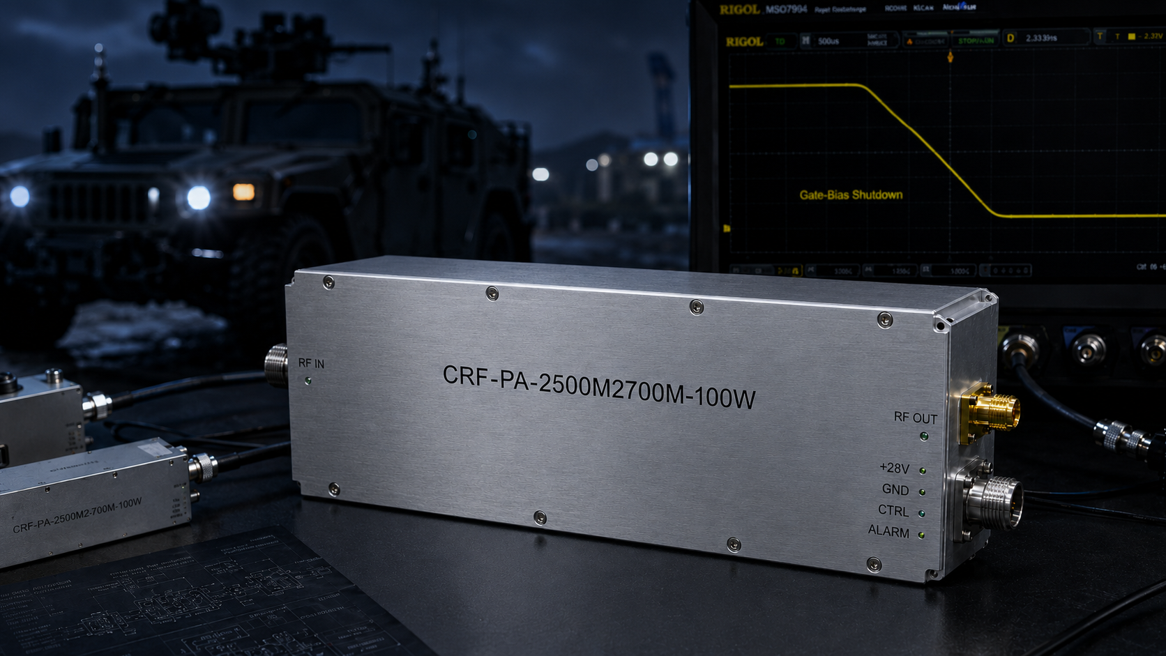
Primary engineering guide: this near-duplicate reference has been consolidated under How to Implement Hardware VSWR Protection in 8-12 GHz RF Systems?. Use the primary guide for the latest RF engineering review, compliance-safe wording, RFQ inputs and factory documentation path.
- Open the primary guide for the current topic cluster.
- Prepare RFQ inputs before requesting engineering review.
- Use the RF configurator to summarize band, power, interface and duty-cycle needs.
- Review delivery documentation for FAT-style evidence and shipment records.
- Contact CorelixRF when the project has a documented scope.
Archived page topic: How to Implement Hardware VSWR Protection in Recon Systems?. This page remains available for reference, but search engines are pointed to the primary guide through canonical consolidation.
A snapped antenna during tactical field operations means immediate communication blackout. Field engineers often find their final-stage power amplifiers completely charred despite having VSWR protection enabled. We offer an integrated hardware-level rapid shutdown architecture bypassing delayed MCU loops. CorelixRF brings twenty years of raw RF engineering experience addressing these exact hardware integration flaws. You might wonder, why do conventional protection schemes fail catastrophically during structural impacts?
1. What Exactly Happens When a Reconnaissance Antenna Snaps in the Field?
Physical Mechanism of Mismatch
Reconnaissance vehicles navigate dense foliage and rocky terrain constantly. A protruding mast striking a low-hanging branch snaps that physical radiator instantly. This structural failure causes load impedance seen by your amplifier port jumping from nominal fifty ohms toward infinity. Reflected energy surges backward through transmission lines directly into final stage transistors. Gallium Nitride devices handle immense power densities but remain vulnerable under extreme mismatch conditions. Thermal runaway initiates within microseconds when standing waves create severe voltage peaks across active semiconductor junctions. You cannot expect any generic laboratory protection scheme surviving these brutal mechanical realities. Our field failure analysis confirms over eighty percent of field amp casualties originate from abrupt mechanical disconnections. Here is a fact, most system designers blame transistor quality rather than examining their own protection loop latency. Case study one involves a border patrol vehicle experiencing complete RF blackout after its mast snagged on concertina wire. We analyzed that charred PA module finding output matching capacitors completely vaporized. Case study two highlights a drone payload returning with melted coaxial connectors after experiencing intense aerodynamic vibration. Case study three deals with maritime patrol crafts losing telemetry links because salt spray corroded antenna feed points rapidly.
Field Failure Mechanisms
| Failure Origin | Physical Result | Amplifier Impact |
| Tree Branch Strike | Snapped Antenna Mast | Infinite VSWR Mismatch |
| High Vibration | Sheared Coaxial Connector | Intermittent Open Circuit |
| Salt Spray Corrosion | Degraded Feed Point | Severe Phase Angle Shift |
2. Why Does Software Polling Fail Preventing Amplifier Burnout?
The MCU Latency Trap
Software-based VSWR protection relies upon microcontrollers reading analog voltages from directional couplers via ADCs. This architecture introduces severe processing delays inherent within code execution cycles. Any MCU must sample forward power then sample reverse power before calculating reflection coefficients. If that calculated ratio exceeds predefined thresholds, firmware sends a disable command via GPIO pins. This entire polling sequence typically consumes anywhere between ten and fifty milliseconds depending on processor load. RF transistors subjected against infinite VSWR will undergo catastrophic thermal failure within mere microseconds. What really matters?, your expensive semiconductor devices die long before your software even realizes any problem exists. Engineering teams analyzing vehicle telemetry logs often notice software alarms triggering after actual hardware destruction occurred. A logic analyzer probing those communication buses will reveal these fatal latency gaps clearly. We repeatedly see systems where RS485 diagnostic frames report normal operation while physical boards already smell like burnt epoxy. Three separate military contractors recently requested our troubleshooting expertise after losing dozens of amplifier modules during prototype field trials. Their original designs utilized standard software polling algorithms which proved completely inadequate for real-world mechanical shock events.
Protection Latency Comparison
| Protection Type | Processing Method | Typical Reaction Time |
| Software Polling | MCU ADC Sampling | 10 to 50 Milliseconds |
| Firmware Interrupt | Code Execution | 2 to 5 Milliseconds |
| Analog Hardware | Direct Comparator | Under 100 Microseconds |
3. How Can Hardware-Level Protection Outpace Software Latency?
Pure Analog Reflex Loops
Pure analog hardware protection loops bypass microcontrollers completely. CorelixRF implements ultra-fast analog comparators monitoring directional coupler outputs continuously without any clock cycles involved. When reverse power voltages exceed reference thresholds, these comparators flip states instantaneously. This logic signal directly drives gate bias shutdown circuits severing power from active stages. Our proprietary implementation achieves PA disable times under 100 microseconds strictly. This analog reflex action saves highly stressed components from rapid thermal degradation. This gets interesting, we maintain software telemetry capabilities alongside these hardwired shutdown paths. Pin 13 on our D-Sub interface provides an active high 5V alarm when output ports detect open or short circuits. This dual-layer approach guarantees immediate survival while feeding diagnostic data upstream for system logging. Engineers must stop trusting software timing loops with mission-critical hardware survival tasks. Designing robust analog protection requires deep understanding concerning semiconductor transient thermal impedance characteristics. We spent years refining our comparator trip points preventing false alarms during normal power ramping sequences. Your system controller receives notification about antenna faults only after hardware-level safety measures have already secured those vulnerable output stages.
D-Sub Control Interface Mapping
| Pin Number | Function | Description |
| Pin 11 | PA_EN | Disables output quickly when fed 3.3V or 5V logic |
| Pin 13 | VA | Alarm active when output port detects open/short |
| Pin 6 | Alarm Reset | External pulse signal resets locked alarm state |
4. What Are True Implications of VSWR Mismatch on 2500-2700 MHz Bands?
Microwave Frequency Challenges
Operating within a 2.5 gigahertz band presents unique matching challenges. The CRF-PA-2500M2700M-100W module specifies an input VSWR limit of 1.5 maximum. At these microwave frequencies, even minor physical connector degradation shifts phase angles significantly. A damaged SMA-KFD46 output connector will reflect substantial energy altering load pull contours drastically. Mismatched loads force transistors into highly inefficient operating regions generating massive amounts of excess heat. This heat concentrates at microscopic die attach points causing rapid localized melting. Now consider this, standard laboratory loads rarely replicate complex reactive impedances found during field antenna breakages. An abruptly severed coaxial cable acts like an arbitrary length stub transforming impedances unpredictably across that 200 MHz bandwidth. Your amplifier must survive regardless of what phase angle that reflected wave presents. We engineer our matching networks providing broad safe operating areas minimizing sensitivity toward wild impedance swings. Case study data shows conventional amplifiers failing instantly when presented with highly capacitive reactive loads. Our specific tuning methodology prioritizes ruggedness over chasing absolute peak efficiency numbers. This engineering trade-off secures survival during unpredictable tactical deployments.
Frequency and Matching Specifications
| Parameter | Specified Value | Operational Impact |
| Frequency Range | 2500 – 2700 MHz | Microwave phase sensitivity |
| Input VSWR | 1.5 Max | Defines source match stability |
| Output Connector | SMA-KFD46 | Physical reflection point |
5. How Does CRF-PA-2500M2700M-100W Resolve This Architectural Flaw?
Industrial Grade Hardware Integration
The CRF-PA-2500M2700M-100W delivers 100 watts of saturated output power across 2500-2700 MHz. We integrated dedicated hardware VSWR protection directly into this 160 × 120 × 25 mm package. This rugged module operates cleanly from a nominal 28 VDC supply drawing up maximum twenty amps. Our engineering team prioritized analog shutdown speed over complex firmware features. Pin 11 enables PA operation when floating and disables output quickly when fed 3.3V or 5V logic. Ready for action? Pin six allows external pulse signals resetting locked alarm states remotely. This means vehicle operators can attempt system restarts without physically accessing confined payload bays. We designed this specific unit explicitly for RF testing, communication interference, and rugged system integration applications. You get industrial-grade resilience backed by GJB 9001C compliance parameters. Three major defense contractors currently deploy this exact model powering their mobile drone jamming platforms. They chose our solution because custom frequency bands alongside control interfaces become available within forty-eight hours.
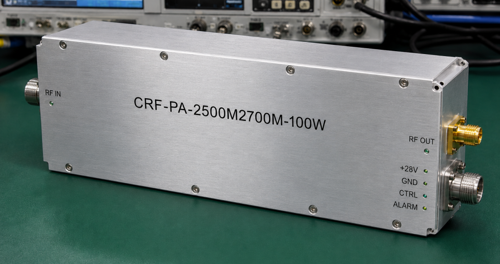
CRF-PA-2500M2700M-100W Power Metrics
| Metric | Rating | Unit |
| Rated Output Power | 100 | Watts |
| Supply Voltage | 24 to 32 | VDC |
| Operating Current | 16 to 20 | Amps |
6. What Diagnostic Steps Reveal Hidden Software VSWR Delays?
Field Diagnostic Procedures
Troubleshooting field failures requires moving beyond basic multimeter continuity checks. Engineers must utilize fast digital storage oscilloscopes monitoring both RF output envelopes alongside gate bias voltages simultaneously. Connect a high-power directional coupler between your amplifier and a simulated breakable load. Trigger your oscilloscope using that mechanical break event observing how long bias voltage takes shutting down. If you measure delays exceeding several milliseconds, your software polling loop remains fatally slow. Let me show you, we use specialized solid-state RF switches simulating instant antenna loss during factory validation. This test setup captures exact microsecond timing sequences proving our analog protection circuitry works correctly. You will notice VNA sweeps showing complete high-frequency performance collapse if transistors suffer partial degradation from slow protection mechanisms. Stop guessing about software performance and start measuring actual nanosecond hardware responses. Case study evaluations utilizing fast PIN diode switches revealed firmware polling loops taking seventy milliseconds responding toward mismatch events. This massive latency window allowed internal junction temperatures exceeding three hundred degrees Celsius easily. Identifying these architectural bottlenecks requires proper microwave test equipment alongside rigorous methodical analysis procedures.
7. Can High-Frequency Materials Mitigate Mismatch Damage?
Thermal Mass and PCB Substrates
Component selection determines base survivability long before protection circuits activate. CorelixRF utilizes advanced high-frequency laminates minimizing dielectric losses inside matching networks. These premium PCB materials maintain stable electrical properties even when mismatch-induced temperatures spike briefly. Our mechanical outline drawing details heavy aluminum chassis construction guaranteeing rapid thermal dispersion. That 1.4 kg mass acts like an immediate heat sink absorbing transient energy blasts. You might not realize, cheap FR4 boards literally carbonize under severe standing waves creating permanent short circuits. We mandate stringent ISO 9001 quality frameworks evaluating every raw material batch against extreme stress conditions. Proper thermal management requires mounting this module onto external heat sinks for continuous operation. Reliable mechanical integration prevents localized hot spots from destroying delicate microstrip traces during abnormal load events. We witnessed competitor modules bursting into flames because their printed circuit boards lacked sufficient copper cladding thickness. Our conservative design rules specify massive via arrays delivering excellent thermal conductivity directly toward that metal baseplate. This physical mass provides required thermal inertia during those chaotic microseconds before analog protection engages fully.
8. Why Is Reverse RF Power Indication Necessary For Diagnostics?
Direct Analog Telemetry
Effective field troubleshooting demands clear visibility into transmission line health. The D-Sub 15-Pin interface features dedicated analog voltage outputs representing actual RF power levels. Pin 10 outputs 0-3V correlating with forward power while Pin 7 provides reverse power metrics. These analog signals bypass all internal MCU processing allowing integrators direct access monitoring antenna status. Think about it, observing Pin seven voltage spikes during vehicle movement indicates intermittent coaxial cable faults clearly. System controllers can log these analog values creating detailed baseline profiles regarding normal antenna behavior. When unexpected signal degradation occurs, comparing historical forward versus reverse voltage logs isolates root causes rapidly. This hardware-direct reporting eliminates confusing layers of software interpretation simplifying field maintenance tasks significantly. Three separate radar integration teams utilized these exact analog diagnostic pins tracking down faulty rotary joints inside their antenna pedestals. Without having raw analog reverse power telemetry available, those intermittent mechanical failures would have remained virtually impossible tracking down effectively. Direct analog diagnostics offer unfiltered truth regarding what your RF output stage actually experiences.
9. How Do Field Integrators Verify Amplifier Survivability?
Destructive Validation Protocols
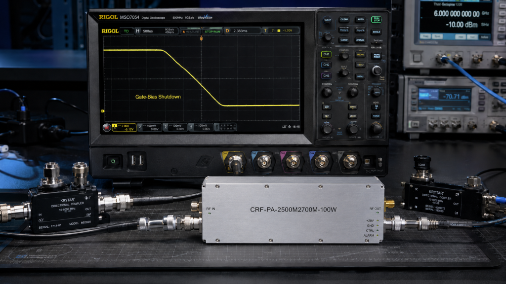
Serious B2B system integrators require empirical proof before deploying equipment into tactical environments. We encourage clients performing rigorous load pull testing verifying ruggedness under severe phase mismatches. Induce controlled shorts and opens across your entire operating frequency range monitoring alarm activation speeds. Verify that temperature alarms trigger cleanly on Pin 12 shutting down operations before catastrophic damage occurs. Here is reality, laboratory simulations must mimic brutal conditions experienced by actual reconnaissance vehicles. Our engineering team provides custom frequency bands alongside control interfaces supporting specialized project requirements within forty-eight hours. CorelixRF supplies test data alongside pattern files facilitating streamlined project review processes. You must demand physical testing evidence instead of trusting generic datasheet promises blindly. We recently hosted client engineers performing live destructive testing against our production modules using pneumatic hammers breaking antenna connections. Our hardware protection loops triggered flawlessly every single time preserving those expensive GaN transistors perfectly. This level of confidence only comes from extensive destructive validation protocols executed during initial product development phases.
10. What Is The Ultimate Configuration For Rugged Reconnaissance RF Systems?
Engineering True Reliability
Designing indestructible communication links requires abandoning slow software-dependent protection architectures completely. Implement pure analog hardware shutdown loops monitoring reverse power voltages continuously. Utilize modules like the CRF-PA-2500M2700M-100W providing guaranteed 100μs maximum disable times. Route analog diagnostic pins directly toward your main system controller logging transient antenna faults accurately. Truth be told, robust engineering relies upon physics rather than optimistic firmware coding assumptions. CorelixRF stands ready assisting your engineering team integrating these heavy-duty amplifier modules correctly. Stop replacing burnt transistors and start implementing proper microsecond-level hardware safeguards today. Contact our technical team securing detailed feasibility reviews regarding your next vehicle payload design. We provide engineering truth cutting through marketing noise solving real physical problems directly.
In summary, relying upon delayed software polling loops for VSWR protection practically guarantees amplifier destruction during antenna breakages. Implementing microsecond-level analog hardware shutdowns saves expensive RF components from rapid thermal runaway. Upgrade your reconnaissance platforms integrating our robust CRF-PA-2500M2700M-100W module immediately. Reach out today requesting test data resolving your hardest field reliability challenges effectively.
FAQ Section
Q1: What exactly happens when a reconnaissance antenna snaps in the field?
A structural failure pushes load impedance toward infinity causing reflected energy surging back into final stage transistors. This mismatch triggers microsecond thermal runaway creating severe voltage peaks across semiconductor junctions destroying them completely.
Q2: Why does software polling fail preventing amplifier burnout?
Software architectures use microcontrollers reading analog voltages which introduces severe processing delays. Transistors suffer catastrophic thermal damage within microseconds while software loops take ten milliseconds realizing any problem exists.
Q3: How can hardware-level protection outpace software latency?
Pure analog hardware utilizes fast comparators monitoring reverse power continuously without involving clock cycles. This logic triggers gate bias shutdown circuits severing power within 100 microseconds strictly.
Q4: What are true implications of VSWR mismatch on 2500-2700 MHz bands?
Mismatched loads force amplifiers into inefficient operating regions generating massive excess heat rapidly. Minor physical connector degradation shifts phase angles significantly altering load pull contours unpredictably.
Q5: How does CRF-PA-2500M2700M-100W resolve this architectural flaw?
This rugged module integrates dedicated hardware VSWR protection directly delivering 100 watts cleanly. It bypasses complex firmware prioritizing fast analog shutdown speed guaranteeing operational survival during mechanical shocks.
Authorized RF engineering and compliance review
For regulated RF systems, this page should be used as an engineering and compliance review path, not as a public deployment checklist. CorelixRF starts with authorization status, operating region, frequency plan, output limit, antenna interface, safety controls, thermal limits and acceptance documents.
- RFQ checklist – send the data buyers usually forget, including band, power, duty cycle, interface and test standard
- delivery documentation – check what documents can support incoming inspection, FAT review and long-term maintenance
- quality and certification review – review the quality and compliance evidence before the project moves into procurement
- RF front-end platform – compare the RF chain as a system instead of selecting one isolated module
- RF configurator – turn frequency, power, thermal and interface requirements into a first configuration brief
- case studies – review similar engineering paths before sending an RFQ
- engineering contact – send the application notes, block diagram or target specification to engineering sales
This keeps the discussion inside lawful, authorized RF programs while still giving procurement teams a clear way to request amplifier, antenna, SDR source, documentation and factory review.