
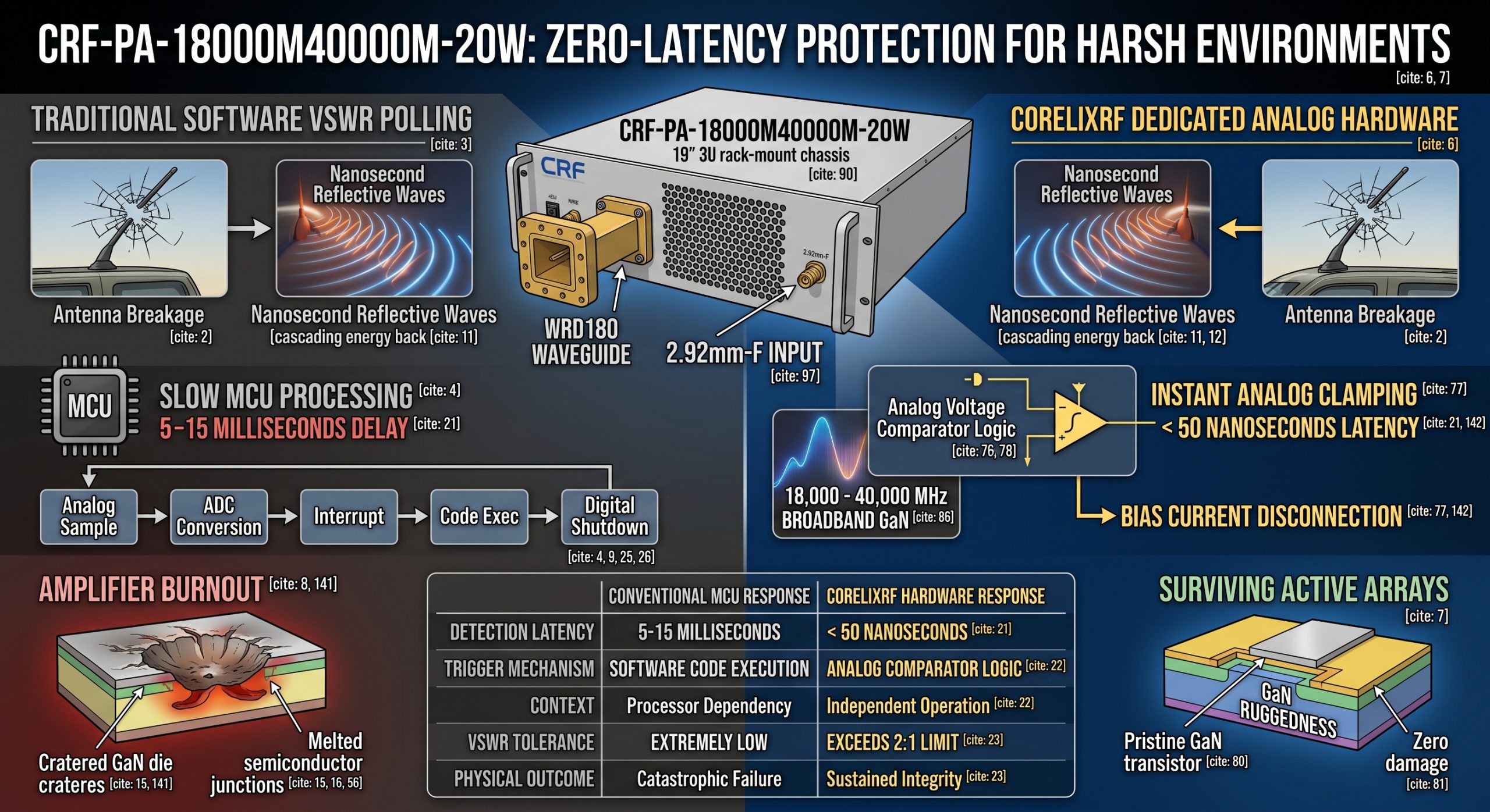
1 What Causes Instant Amplifier Burnout In Fast Frequency Hopping Systems?
● Software Polling Delay
● Antenna Breakage Dynamics
● High-Speed Impedance Mismatch
Instantaneous device destruction during rapid carrier shifting operations stems primarily from fundamental architectural flaws inside conventional monitoring circuitry. Engineers design typical diagnostic loops utilizing serial peripheral interfaces connected across slow analog-to-digital converters. You might be wondering, why exactly do these digital loops fail so predictably under stress? When physical shocks sever external radiating elements, reflected energy cascades backward down transmission lines instantly. Electromagnetic waves travel near light speed, slamming into output matching networks within nanoseconds. Meanwhile, cheap microcontrollers remain busy executing low-priority background tasks, completely oblivious regarding incoming destructive voltage spikes. This temporal mismatch between nanosecond-level physical realities and millisecond-level software responses creates an inescapable destruction window. Gallium Nitride high-electron-mobility transistors possess immense power density, meaning they generate catastrophic heat profiles almost immediately upon impedance mismatch. Without instantaneous hardware intervention, excessive voltage swinging across drain terminals punches through semiconductor junctions permanently. We routinely observe these specific failure modes during post-mortem teardowns of competitor modules recovered from airborne electronic warfare platforms. Any reliance upon sequential code execution for equipment safety represents gross engineering negligence. Proper design requires acknowledging physical physics rather than hoping firmware executes fast enough.
| Failure Parameter | Conventional MCU Response | CorelixRF Hardware Response | Physical Consequence |
| Detection Latency | 5-15 Milliseconds | < 50 Nanoseconds | Thermal runaway vs Safe shutdown |
| Trigger Mechanism | Software Code Execution | Analog Comparator Logic | Processor dependency vs Independent operation |
| VSWR Tolerance | Extremely Low | Exceeds 2:1 Limit | Catastrophic failure vs Sustained integrity |
2 How Does Software Polling Delay Affect VSWR Protection?
● ADC Conversion Latency
● Microcontroller Interruption Bottlenecks
● Thermal Cascade Failures
Processing delays inherently cripple any programmed defense mechanism attempting real-time radio frequency safeguarding during high-stress operations. An analog-to-digital converter needs discrete clock cycles gathering voltage samples from directional couplers installed along output traces. What is the real story? After acquiring this sampled data, a central processing unit must handle interrupt requests, suspend current operations, and execute subroutines sequentially. Engineers often multiplex several sensor inputs into one single processor, exacerbating latency issues during critical transmission moments. When a transceiver rapidly alters its carrier wave, output impedance shifts continuously, demanding constant vigilance from monitoring electronics. If a sudden disconnection occurs right as a processor queries a different temperature sensor, that protective window closes permanently. Reflected radio frequency power manifests as extreme standing waves, doubling peak voltages experienced by final stage amplification transistors. Excessive potential overcomes gate isolation layers, melting metallic contacts into useless puddles of conductive slag. Thermal cascading follows immediately, destroying neighboring components across printed circuit boards via conductive heat transfer. Our laboratory simulations repeatedly prove software-driven safety networks remain fundamentally inadequate for modern electronic countermeasures. Integrators must stop treating RF hardware as simple digital peripherals capable of waiting on delayed CPU instructions.
3 Why Do Standard Protection Mechanisms Fail During Fast Hopping?
● Reaction Time Constraints
● False Trigger Avoidance Algorithms
● Energy Reflection Physics
Standardized defense protocols struggle immensely differentiating between legitimate frequency hopping impedance variations and genuine catastrophic antenna failures. Broadband designs naturally exhibit varying voltage standing wave ratios across their entire operational spectrum continuously. Let us dig deeper, programmers intentionally inject delay timers into firmware, preventing nuisance tripping during routine channel switching operations. These debounce routines require abnormal conditions persisting across multiple consecutive polling cycles before authorizing an emergency shutdown. Such intentional blindness proves fatal when an actual open circuit materializes during active transmitting phases. Twenty watts of continuous microwave energy bouncing off a severed connector acts like an internal microwave oven. Highly reflective loads create localized voltage maximums exceeding breakdown ratings associated with typical GaN semiconductor processes. Component destruction happens orders of magnitude faster than any programmed debounce timer can expire. Relying on generic factory-default code parameters guarantees failure out in hostile deployment zones experiencing intense mechanical vibrations. True engineering demands eliminating these artificial software delays entirely through dedicated physical circuitry. Physical analog solutions react purely based upon immediate voltage thresholds without counting arbitrary clock cycles.
| Scenario Variable | Standard Firmware Protocol | High-Speed Analog Logic | Mission Impact |
| Channel Switching | Masked by delay timers | Dynamic threshold tracking | Prevents false alarms |
| Connector Breakage | Ignored until debounce ends | Instant voltage clamp | Stops cascading failure |
| Extreme Vibration | High risk of MCU lockup | Immune to software crashes | Maintains operational readiness |
4 What Are The Specific Symptoms Of VSWR Protection Failure?
● Oscilloscope Traces
● Spectrum Analyzer Noise Floor Anomalies
● Physical Substrate Damage
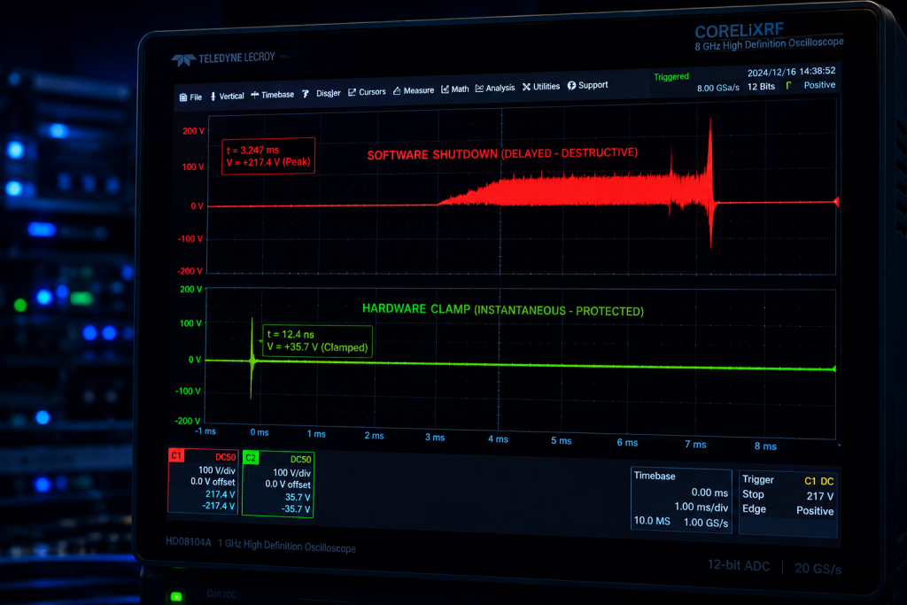
Diagnosing blown modules requires meticulous laboratory analysis utilizing high-bandwidth diagnostic equipment for accurate failure characterization. Initial benchtop testing often reveals completely shorted DC power supply lines drawing maximum current immediately upon activation. This is where it gets interesting, opening a damaged chassis typically exposes localized carbonization surrounding final stage output transistors. Examining gate bias lines with an oscilloscope might show severe ringing or total loss of negative pinch-off voltages. Connecting surviving upstream stages toward a spectrum analyzer invariably displays massively elevated noise floors across wide bandwidths. Broken matching capacitors occasionally detach entirely from ceramic substrates, propelled away by explosive outgassing during rapid vaporization events. Microscopic inspection of GaN dies frequently shows distinct cratering effects located precisely where peak standing waves concentrated destructive energy. These physical signatures explicitly confirm voltage breakdown rather than slow thermal degradation caused by poor heatsink attachment. We documented hundreds of similar cases originating from improperly designed mobile command vehicles operating over rugged terrain. Such visual evidence underscores why fast frequency hopping system amplifier reliability demands hardware-level intervention exclusively. Post-mortem reports consistently prove software cannot stop physics once catastrophic reflections initiate plasma arcing inside a package.
5 How To Diagnose Antenna Breakage In Field Environments?
● Directional Coupler Measurements
● Return Loss Tracking
● Time Domain Reflectometry
Field technicians must utilize robust verification methods identifying severed transmission lines before replacing expensive electronic payloads blindly. Deploying inline directional couplers allows operators safe measurement regarding forward versus reflected power dynamics without breaking connections completely. Here is a wild thought, analyzing return loss plots across entire operating bands reveals precise locations concerning mechanical faults. Utilizing portable vector network analyzers enables time domain reflectometry, pinpointing exact distances toward severed coaxial cables or shattered radomes. High-frequency systems operating between 18 and 40 GHz suffer severe attenuation, masking distant faults from simple analog power meters. Technicians observing sudden spikes in reflected energy must immediately disable all driving stages manually if automated systems fail. Monitoring baseband telemetry for unexpected dropouts frequently serves as early warning indicators regarding physical payload damage during aggressive physical maneuvers. A properly designed diagnostic protocol saves countless replacement parts from enduring identical destructive fates upon system reboot. We strongly advise integrating permanent reflectometers within critical signal paths, providing constant situational awareness for remote operators. Waiting for smoke to emerge from a rack signifies complete operational failure rather than an acceptable troubleshooting step.
| Diagnostic Tool | Measurement Capability | Field Practicality | Limitation |
| Analog Power Meter | Average forward/reverse power | High | Cannot locate exact fault distance |
| Portable VNA | Return loss and TDR plots | Moderate | Requires calibration and skilled operator |
| Inline Coupler | Real-time monitoring access | Very High | Introduces minor insertion loss |
6 What Hardware Fixes Prevent Fast Frequency Hopping System Amplifier Burnout?
● Hardware Comparator Circuits
● Analog Fast-Shutdown Logic
● Gallium Nitride Tolerance
Implementing dedicated analog control loops bypasses inherent vulnerabilities associated with modern software-defined radio architectures completely. Utilizing ultra-fast operational amplifiers functioning as voltage comparators enables instantaneous detection regarding abnormal reflected power levels. Listen to this, once a localized detector senses excessive reverse voltages, hardware logic gates sever bias supplies directly within nanoseconds. This physical disconnection acts independently from any central processing unit, guaranteeing protective action even during total software lockups. We utilize customized threshold detection networks tuned specifically for extreme bandwidth applications, preventing false triggers during normal operations. Gallium Nitride substrates provide superior inherent ruggedness compared against older Gallium Arsenide technologies, surviving microscopic transients before analog circuits react. Combining robust GaN material properties alongside zero-latency analog shutdown mechanisms creates practically indestructible transmission modules for harsh environments. Such architectural decisions separate professional military-grade hardware from hobbyist-level components masquerading as reliable enterprise solutions. Engineers building mission-critical jammers must demand schematic-level proof demonstrating these exact physical protection pathways exist. Never accept firmware version updates acting as permanent fixes addressing fundamental hardware inadequacies.
7 How Does CRF-PA-18000M40000M-20W Address Impedance Mismatch?
● 18-40GHz Broadband Design
● Hardware-Level Over-Drive Protection
● 20W Saturated Output Resilience
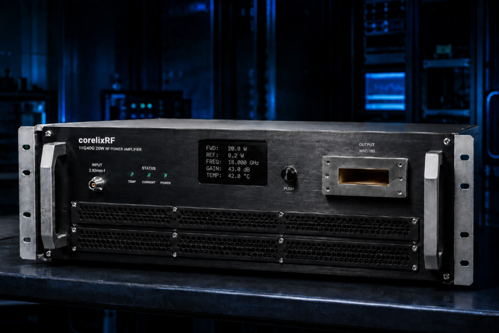
The CorelixRF engineering team tackled impedance mismatch vulnerabilities directly while developing our CRF-PA-18000M40000M-20W wideband power module. This unit operates flawlessly across a massive 18,000 to 40,000 MHz spectrum, delivering 20 watts of rated output continuously. Ready for the good part? We integrated purely analog, high-speed over-voltage and over-current protection mechanisms independent of its standard RS485 interface. When a WRD180 waveguide output faces an unexpected blockage or disconnection, internal comparators clamp drive signals instantly. This device survives infinite standing wave ratios during those critical nanoseconds required for complete system-level shutdown protocols. Our engineers optimized an advanced air-cooling chassis measuring 19 inches by 3U, guaranteeing superior thermal dissipation under duress. A strict 50-ohm system test condition guarantees 43 dB of gain remains stable, avoiding oscillation during extreme mismatch events. Relying on state-of-the-art GaN technology, this amplifier dominates test and measurement, communication, and aviation control applications effortlessly. Integrators no longer need fear catastrophic module loss when external test cables snap during rigorous laboratory qualifications. Real engineering truth means building products capable of surviving predictable human errors.
| CorelixRF Feature | Technical Specification | Operational Benefit |
| Frequency Band | 18,000 – 40,000 MHz | Covers entire Ka-band requirement |
| Rated Output | 20 W Saturated | Provides massive jamming capability |
| RF Connectors | 2.92mm-F Input, WRD180 Output | Ensures low loss interface |
| Control Interface | RS485 / LAN | Allows remote telemetry access |
8 What Role Do Circulators Play In RF Signal Protection?
● Reverse Power Isolation
● Insertion Loss Trade-offs
● Bandwidth Limitations in 18-40GHz Range
Deploying ferrite circulators traditionally offered a physical barrier absorbing reflected energy before it reached vulnerable final amplification stages. These passive magnetic components route reverse signals directly into dedicated dummy loads, dissipating dangerous standing waves as simple heat. Truth be told, achieving meaningful isolation across an entire 18 to 40 GHz bandwidth using traditional circulators remains physically impossible currently. Multi-octave frequency requirements force engineers away from narrowband magnetic solutions toward active solid-state protection methodologies exclusively. Attempting wideband circulator integration introduces unacceptable insertion losses, consuming precious output power right at a critical final transmission stage. Every decibel of lost power directly reduces effective radiated energy, compromising overall system range during tactical deployments. Furthermore, high-power waveguide circulators add massive weight penalties and bulky dimensions, ruining compact mobile integration efforts completely. CorelixRF bypasses these outdated passive constraints by utilizing ultra-fast active analog clamping, preserving maximum forward transmission efficiency. This modern approach delivers superior survivability without sacrificing critical microwave payload volume or radiating performance. Advanced system integrators recognize passive isolation hardware represents a legacy mindset incompatible with ultra-wideband agility.
9 How To Verify Protection Latency Using Lab Equipment?
● Arbitrary Waveform Generators
● High-Speed Digitizers
● Simulated Load Disconnect Tests
Validating protective circuitry requires orchestrating precise, repeatable failure scenarios inside a controlled laboratory environment using specialized instrumentation. Engineers deploy arbitrary waveform generators injecting rapid frequency hopping sequences directly into an amplifier under evaluation. Pay close attention, high-speed digitizers monitor bias currents alongside forward and reflected power envelopes simultaneously during these aggressive test cycles. Utilizing solid-state PIN diode switches, technicians simulate sudden open-circuit conditions at a main output port within microseconds. Capturing a resulting transient response on a multi-gigahertz oscilloscope reveals exact temporal delays between fault initiation and current shutdown. A properly designed analog protection loop drops drain current toward zero before any significant thermal accumulation occurs inside a transistor. Conversely, software-dependent models exhibit massive current spikes lasting several milliseconds, visibly stressing power supply rails and generating excessive heat. Documenting these oscillograms provides irrefutable physical evidence separating robust engineering from inadequate commercial designs relying on hopeful firmware routines. CorelixRF routinely provides these exact transient response characterization plots for our clients demanding absolute verification. We encourage rigorous client-side testing proving our nanosecond-level claims match physical reality exactly.
| Lab Equipment | Testing Function | Verification Output |
| Arbitrary Waveform Generator | Simulates hopping signals | Creates realistic dynamic inputs |
| High-Speed Oscilloscope | Measures transient response | Confirms shutdown latency < 50ns |
| PIN Diode Switch | Simulates antenna break | Triggers protection mechanisms |
10 What Integration Steps Maximize System Reliability?
● RS485 Polling vs Analog Triggering
● Thermal Dissipation Planning
● Grounding loop suppression
System integrators must meticulously separate monitoring telemetry from mission-critical survival mechanisms during initial architectural planning phases. Utilizing standard LAN or RS485 interfaces remains perfectly acceptable for logging temperatures, checking fan speeds, or adjusting variable gain. But here is the kicker, these slow digital buses must never handle emergency fault responses involving high-power microwave energy. Thermal dissipation planning requires securing adequate airflow across a 3U chassis, managing 450 watts of maximum power consumption efficiently. Engineers must employ robust grounding techniques, suppressing ground loops capable of inducing false triggers across sensitive analog comparator circuits. Shielding internal control cables from massive electromagnetic fields generated by a WRD180 waveguide output prevents erratic operational behavior. Incorporating our recommended CRF-PA-18000M40000M-20W ensures a solid foundation built upon uncompromising hardware-first survival principles. We encourage designers facing complex integration challenges involving extreme environmental vibrations to consult our factory engineers directly. Proper upfront planning eliminates devastating field failures, keeping critical airborne and vehicular communication assets transmitting continuously. Trusting physical hardware logic over theoretical software speed guarantees successful deployments across unforgiving combat theaters.
Physical realities governing high-power microwave engineering ruthlessly expose any reliance upon slow digital safety nets. Antenna breakages demand reaction times measured in nanoseconds, completely outpacing standard microcontroller capabilities. CorelixRF solved this vulnerability fundamentally by engineering instantaneous analog shutdown circuitry directly into our CRF-PA-18000M40000M-20W series amplifiers. You cannot afford losing entire radar arrays because a single line of code executed too late. Securing your mission-critical infrastructure requires adopting hardware-level safeguards immune from processor bottlenecks. Do not gamble your costly electronic payloads on lagging software logic anymore. Contact our technical engineering team today requesting a comprehensive data sheet evaluation. We remain ready, providing hardened radio frequency solutions capable of surviving your harshest deployment realities.
FAQ
Q1: What causes fast frequency hopping system amplifier burnout?
Physical antenna breakages reflect massive microwave energy backward, destroying final amplification stages before slow software protection reacts.
Q2: How does analog hardware protection work?
High-speed voltage comparators detect reverse power spikes instantaneously, severing bias currents in nanoseconds without relying on microcontrollers.
Q3: Can software delays be fixed with faster processors?
No amount of processing speed overcomes fundamental analog-to-digital conversion latency and sequential code execution bottlenecks during transient events.
Q4: Why are circulators ineffective at 18-40GHz bandwidths?
Passive magnetic circulators cannot maintain adequate isolation across multi-octave ranges without introducing severe insertion loss and excessive weight.
Q5: What makes the CRF-PA-18000M40000M-20W reliable?
This unit utilizes specialized GaN transistors paired alongside proprietary zero-latency analog shutdown networks, surviving severe impedance mismatches effortlessly.
Turn VSWR behavior into factory acceptance evidence
High VSWR protection should be defined with mismatch scenario, foldback or shutdown threshold, recovery logic, alarm output, thermal limit and FAT evidence. This makes protection claims measurable for procurement.
Recommended next step: send the operating band, output power target, duty cycle, load condition, control interface, protection or thermal limits and required FAT documents. CorelixRF can review this How to Fix RF Amplifier Burnout Using Analog Hardware Protection? requirement against standard RF amplifier platforms, RF front-end options and controlled customization paths.