
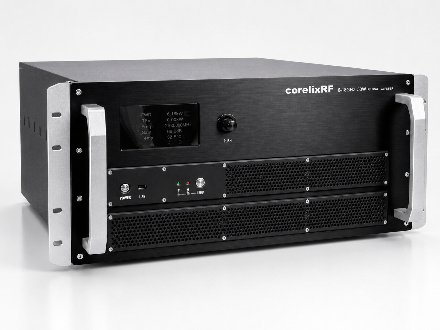
System integrators face catastrophic hardware failures when RF components encounter severe reflection conditions unexpectedly. Software polling delays routinely cause expensive solid-state modules melting down completely before digital protection circuits manage triggering any safety protocols. CorelixRF delivers hardware-based VSWR suppression methods mitigating these exact thermal breakdowns reliably across extreme military deployments. You might be wondering how extreme component degradation happens rapidly during routine operational missions abroad. We will examine actual field data detailing why traditional microcontrollers fail during high-speed band switching routines.
1. What Triggers the Hidden Fault in Fast Frequency Hopping Systems?
Rapid Band Modulation
Fast frequency hopping architectures demand rapid switching between discrete transmission bands constantly. Electronic warfare transceivers jump across broad spectrums within bare microseconds avoiding enemy jamming attempts. This rapid modulation stresses RF power amplifiers continuously driving components toward physical breaking points. Unexpected impedance mismatches generate massive standing waves traveling back toward exposed GaN dies rapidly. Engineers assume main processing units handle these reflections effectively using standard firmware protection algorithms. But here is the catch. Standard microcontrollers rely upon software polling cycles checking sensor voltages periodically throughout execution loops.
The Polling Lag
A typical CPU might scan reverse power channels every fifty milliseconds precisely. An antenna cable snapping under mechanical vibration creates an immediate open circuit condition physically. Fifty milliseconds represents an absolute eternity for microwave transistors operating at fifty watts continuously. Forward energy reflects entirely back into your output matching network destroying active components. Voltages exceed semiconductor breakdown thresholds almost instantaneously creating permanent hardware short circuits. You witness smoke escaping from rack enclosures long before processors register anomalous voltage readings.
System Fault Trigger Variables
| Parameter | Description |
| Software Polling Rate | 50 milliseconds typical |
| Transistor Breakdown Time | < 1 millisecond |
| Frequency Range | 6,000-18,000 MHz |
| Reflection Coefficient | 1.0 (Open Circuit) |
2. Why Does Software Polling Fail to Protect RF Amplifiers?
Sequential Execution Flaws
Software loops operate sequentially executing instructions line by line continuously without interruption. Microcontrollers read forward power, then reverse power, then internal temperature sequentially checking status. This sequential operation creates inherent blind spots during rapid dynamic electrical failure events. A sudden impedance shift happens entirely within your analog domain immediately lacking any delay. Code must complete its current loop before reading fresh VSWR values from sensor registers. Think about that for a minute. If faults happen exactly after reverse power sensors transmit data, total destruction follows shortly. Your system waits a full cycle before noticing localized voltage spikes developing across transistors. High-power solid-state modules demand real-time analog intervention maintaining absolute survivability during intense combat missions.
Microsecond Latency Damage
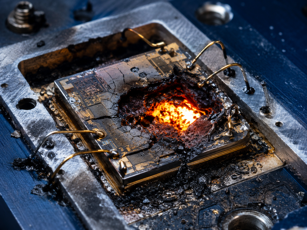
A 50W output module generates intense localized thermal spikes during heavy mismatch scenarios. Junction temperatures belonging to gallium nitride exceed absolute maximum ratings instantly melting internal structures. Engineers building jammer systems overlook this microsecond-level latency issue focusing purely upon user interfaces. They write elegant code handling graphical displays brilliantly lacking core RF physics understanding entirely. RF physics simply does not respect processor clock cycles nor interrupt request priorities whatsoever. Let us look closer. Fifty watts hitting broken cables forces standing waves forming violently reflecting backward immediately. Voltage standing wave ratios spike toward infinity within nanoseconds destroying matching networks completely. CorelixRF engineers measure destructive transients using high-speed digital storage oscilloscopes analyzing failure mechanisms directly.
Digital System Latency Comparison
| Subsystem | Typical Reaction Time |
| Software Polling Loop | 20 to 100 milliseconds |
| ADC Sampling Rate | 5 to 50 microseconds |
| Analog Hardware Trigger | < 500 nanoseconds |
| GaN Die Breakdown | 1 to 2 milliseconds |
3. How Do Antenna Breakages Occur in High-Vibration Deployments?
Mechanical Shock Factors
Mobile electronic countermeasures endure extreme mechanical shocks constantly during rugged field missions globally. Tracked armored vehicles transfer brutal low-frequency vibrations directly into delicate equipment racks unhindered. Antenna masts whip violently while operators navigate rugged terrain driving at high vehicle speeds. Here is the deal. Mechanical forces concentrate heavily upon rigid coaxial connections creating massive stress fracture points. The output N-Female connector bears immense shear loads during continuous cross-country travel missions. Metal fatigue accumulates microscopic cracks across central conductor pins silently degrading transmission quality slowly. A harsh bump severs internal mating surfaces completely isolating your radiating elements abruptly. Sudden separation creates a perfect open circuit at your amplifier output port destroying everything.
Erratic Contact Chaos
You rarely find intermittent connection issues during stationary climate-controlled laboratory testing environments. Network analyzers show pristine fifty-ohm matches while sitting calmly on sturdy workbench tops. Field environments introduce random multi-axis shaking tearing apart poorly secured cable assemblies rapidly. It gets worse. Operators notice degraded transmission ranges intermittently before complete communication blackouts happen entirely. Fractured pins touch briefly during certain vibration resonance frequencies causing chaotic impedance swings unpredictably. Erratic contact generates massive electrical noise confusing software protection algorithms completely masking real threats. Software averages out short spikes ignoring impending disaster waiting just around the corner. Once gaps widen permanently, full 50W output power reflects backward melting internal circuit boards.
Common Field Failure Modes
| Failure Type | Physical Cause |
| Center Pin Shear | Vertical axis shock |
| Thread Loosening | High-frequency vibration |
| Solder Joint Crack | Thermal cycling stress |
| Dielectric Melting | Reflected RF heating |
4. What Are the Physical Mechanics of Instantaneous PA Destruction?
Solid-State Physics Breakdown
Understanding RF transistor failure requires studying semiconductor solid-state physics analyzing electron mobility limitations. Gallium nitride devices operate utilizing high electron mobility across extremely thin epitaxial layers. Under matched conditions, thermal energy dissipates efficiently downward into heavy aluminum chassis heatsinks. Open circuits force voltage and current waves entirely out of phase maximizing internal stress. What does this mean for you? Drain voltages swing far beyond designed thirty-two volt maximum limits instantly exceeding tolerances. Massive overvoltage punches right through delicate semiconductor depletion regions shattering crystalline lattice structures permanently. Physical ruptures cause irreversible short circuits destroying expensive amplifier modules beyond localized repair possibilities. You cannot fix damaged transistor dies using firmware updates nor simple system power reboots.
Thermal Runaway Cascades
Thermal runaway represents another distinct physical mechanism destroying active RF components during field operations. Reflected energy turns output matching networks into highly efficient localized ceramic heater elements. Local hot spots develop across transistor dies faster than copper carriers conduct heat away. Operating temperature limits state maximum fifty degrees Celsius for safe sustained continuous transmissions. Severe mismatch forces microscopic junctions exceeding two hundred degrees melting protective encapsulate materials instantly. Consider this scenario. Fifty-watt continuous wave signals bounce back into tiny millimeter-sized semiconductor chips concentrating energy tightly. Power density becomes comparable with heavy industrial laser cutting equipment vaporizing precious metal traces. Gold bond wires melt vaporizing into conductive smoke clouds shorting adjacent bias circuitry immediately. The resulting short circuit destroys main twenty-eight-volt power supplies simultaneously compounding hardware damages further.
Amplifier Hardware Failure Mechanisms
| Mechanism | Primary Cause |
| Voltage Breakdown | Standing wave peak voltage |
| Thermal Runaway | Concentrated reflected heat |
| Electromigration | Excessive localized current |
| Bond Wire Melting | Sudden massive overcurrent |
5. How Can Engineers Diagnose This VSWR Delay Issue in the Field?
Direct Analog Measurement
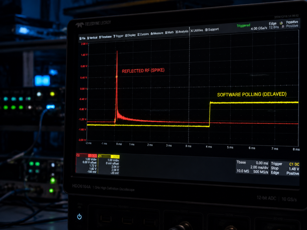
Troubleshooting burned amplifiers requires bypassing system software completely during initial diagnostic testing phases. Engineers must attach independent measurement tools directly against bare RF outputs checking raw signals. Directional couplers placed inline extract forward and reverse power samples isolating directional traveling waves. Let me explain. You feed sampled RF signals into fast crystal detectors converting microwave energy into DC. Detector outputs connect straight into multi-channel digital storage oscilloscopes displaying real-time voltage transient curves. Trigger your scope using primary system transmission command signal lines establishing precise timing references. This setup captures exact timing relationships between RF output bursts and returning reflection spikes.
Simulating Destructive Events
Simulating antenna breaks involves using specialized fast solid-state switches interrupting load paths abruptly. Configure your switch dumping loads into open circuits abruptly while transmitting continuous wave signals. Oscilloscope screens display reverse power spiking sharply across grids proving massive mismatch events occurring. Here is the kicker. Monitor DB9 Pin 3 PTT control lines simultaneously capturing automated shutdown response times directly. PTT lines dropping milliseconds after reflection spikes prove software failed reacting quickly enough definitively. Visual gaps between reflection events and shutdown signals prove latency destroying hardware units consistently. Hard evidence convinces project managers that firmware cannot beat physical laws governing microwave propagation. Deploy pure analog hardware interlocks preventing catastrophic field failures saving massive future replacement budgets.
Hardware Field Diagnostic Equipment
| Tool | Application Purpose |
| Directional Coupler | Sampling directional traveling waves |
| Crystal Detector | Converting RF into DC |
| Oscilloscope | Capturing nanosecond timing |
| Fast RF Switch | Simulating cable breaks |
6. Why Is Hardware-Level VSWR Protection Superior to Software Algorithms?
Instantaneous Analog Logic
Hardware-level protection relies upon purely physical analog voltage comparator circuits reacting at light speed. Analog multipliers calculate reflection coefficients instantaneously without executing complex mathematical code libraries whatsoever. Reverse voltage exceeding predetermined thresholds triggers hardware latches immediately isolating delicate transistor gate biases. Why does this matter? Latches mechanically cut gate bias voltages closing transistors instantly stopping further power generation completely. Shutdown sequences complete within few hundred nanoseconds reliably regardless of external processing unit loads. No lines of code parse data and no operating systems allocate memory delaying actions. Physical speed governing electrons moving through copper traces dictates absolute minimal possible reaction times. Deterministic behavior guarantees survival regardless of what main CPUs process during chaotic electronic warfare.
Unpredictable Processing Jitters
Software architectures inherently introduce unpredictable jitters executing complex mathematical routines continuously sharing limited resources. Busy processors handling incoming Ethernet packets delay checking critical ADC registers risking hardware destruction. Hardware comparators remain dedicated solely toward monitoring one specific safety parameter endlessly without distraction. Think of it this way. Analog protection acts like physical pressure relief valves protecting industrial steam boilers mechanically. Software acts like humans watching gauges attempting turning valves manually after hearing loud explosions. Explosions happening in microseconds mean human-equivalent software reactions always fail preventing catastrophic equipment losses. B2B clients demand equipment surviving harsh treatment without requiring factory repairs disrupting tactical operations. Hardware interlocks deliver rugged reliability missing from cheaper commercial alternatives utilizing generic microcontrollers exclusively.
7. How Does the CRF-PA-6000M18000M-50W Solve the Reflection Problem?
Built-in Hardware Immunity
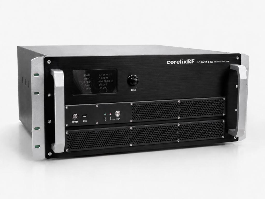
The CRF-PA-6000M18000M-50W incorporates dedicated ultra-fast analog VSWR suppression architecture conquering reflection issues completely. CorelixRF engineers designed built-in protection circuits operating independently from RS485 digital communication buses entirely. This module integrates directional detectors directly onto high-frequency microstrip lines sampling power waves instantly. Ready for the good part? Detectors feed high-speed comparators hardwired straight into bias controllers shutting down operations locally. N-Female output connectors shearing off flip comparators instantly cutting current flowing into GaN devices. Protection activates shutting down RF drives before first reflected waves return completing round trips.
Autonomous Self-Preservation
This specific model handles input VSWR up to 2:1 normally without triggering fault conditions. Encountering massive open circuits forces internal hardware taking over completely bypassing external commands. Internal protection encompasses over-voltage, over-temperature, over-drive, and severe VSWR events handling multiple threats simultaneously. The system never waits for commands via DB9 Pin 1 executing survival protocols immediately. It protects 6,000-18,000 MHz GaN amplification stages entirely on its own autonomous analog logic. Self-preservation capabilities save system integrators thousands reducing field replacements increasing overall mission success rates. Dark industrial designs house brains reacting faster than any digital microcontroller installed upstream perfectly.
8. What Role Do DB9 Pin Definitions Play in Real-Time Diagnostics?
Raw Telemetry Access
While hardware handles emergency shutdowns seamlessly control interfaces provide vital telemetry mapping health trends. The DB9 connector offers real-time analog voltage outputs tracking system health continuously during operations. DB9 Pin 6 delivers forward power monitor detection voltage outputs constantly updating central consoles. DB9 Pin 7 supplies critical reverse power monitor detection voltage outputs predicting future failures. Here is the secret. Engineers use pins feeding raw analog data straight into separate high-speed data acquisition loggers. Analog readouts bypass RS485 digital lag revealing pure hardware truth without polling cycle delays.
Predictive Maintenance Modeling
Integrating monitor pins allows host systems predicting failures before catastrophic mechanical separations happen entirely. Gradually increasing voltages on Pin 7 indicate deteriorating antenna connections requiring immediate physical inspection. Maintenance crews replace damaged cables long before hardware latches trigger preventing sudden transmission dropouts. Also DB9 Pin 8 provides direct temperature detection voltage outputs reading chassis thermal states. Map voltages creating detailed baselines tracking normal operational parameters charting expected thermal rise curves. Deviations from baselines alert operators regarding mechanical degradation occurring outside armored vehicle external hulls. The CRF-PA-6000M18000M-50W acts as both power amplifier and diagnostic sensor simultaneously monitoring RF links.
9. How Does GaN Technology Handle Mismatched Loads Under 50W Output?
Superior Material Ruggedness
Gallium Nitride substrates offer vastly superior ruggedness compared with legacy Gallium Arsenide semiconductor technologies. CorelixRF leverages advanced GaN technology achieving 50W rated output power safely across broad spectrums. High breakdown voltages characterizing GaN naturally resist electrical arcing during extreme transient voltage spikes. This is where it gets interesting. Materials withstand higher operating temperatures providing larger thermal safety margins avoiding instant die melting. Modules maintain maximum noise floors around -40 dBm/MHz despite driving heavy non-linear reactive loads. 28V DC power supplies drive wideband transistors achieving aggressive efficiency minimizing wasted heat generation.
Precision Thermal Management
GaN remains vulnerable without proper engineering implementation managing intense heat fluxes during continuous operation. Achieving 50 dB gain from 6,000 to 18,000 MHz requires precise matching network tuning. Mismatches occur forcing GaN dies absorbing massive reflected thermal energy heating substrates extremely quickly. Air cooling methods rely upon efficient thermal transfer routing heat through aluminum baseplates rapidly. CorelixRF utilizes specialized eutectic die attach processes minimizing thermal resistance dramatically improving heat flow. Efficient transfer allows GaN transistors surviving brief microseconds before hardware protection engages isolating power. You gain ruggedness from advanced materials paired tightly with ultra-fast analog interlock safety mechanisms.
10. What Are the Next Steps for Evaluating the CRF-PA-6000M18000M-50W?
Physical Validation Testing
System integrators require rigorous physical verification validating hardware protection claims themselves utilizing extreme testing. CorelixRF supplies test data and pattern files supporting detailed project reviews directly evaluating compatibility. Integrate sample units into aggressive vibration fixtures simulating tracked vehicle cross-country travel environments accurately. What is the real story? Disconnect RF outputs while transmitting full power checking actual analog protection response times physically. Measure breakdown survivability using directional couplers capturing oscilloscope traces proving nanosecond reaction speeds definitively. $330\times200\times60$ mm package sizes fit easily within standard test benches streamlining laboratory integration processes.
Embracing Analog Reliability
We encourage breaking components during laboratory testing rather than experiencing catastrophic tactical field failures. Connect DB9 interfaces logging analog monitor voltages during experiments charting exact failure mode signatures. Observe built-in protection limiting harmonics strictly below -10 dBc consistently preventing adjacent band interference. Empirical evidence proves superiority characterizing pure analog hardware logic outperforming complex software algorithms easily. Stop relying upon slow microcontrollers safeguarding expensive microwave transmission chains blindly without analog backups. Adopt true engineering solutions reflecting harsh realities governing mobile tactical deployments protecting system integrity.
Final Thoughts Fast frequency hopping systems destroy standard amplifiers due to software polling delays constantly. CorelixRF solves this using ultra-fast analog hardware protection inside the CRF-PA-6000M18000M-50W module. GaN-based engineering guarantees true survivability against sudden open circuits interrupting mission critical links. Upgrade RF architectures protecting valuable investments from catastrophic mechanical failures destroying unprotected equipment today.
FAQ
Q1: What is the main cause of amplifier failure in fast frequency hopping systems?
The primary cause involves software polling delays failing reacting quickly when antennas break unexpectedly. This lag allows severe reflected power melting semiconductor junctions before digital protection circuits trigger.
Q2: How does the built-in protection of the CRF-PA-6000M18000M-50W work?
It uses high-speed analog hardware latches bypassing slow microprocessors shutting down RF drives instantly. This purely physical reaction triggers immediately upon detecting severe VSWR conditions saving transistor dies.
Q3: What is the frequency range and power output of this CorelixRF amplifier?
This specific wideband module operates between 6,000 and 18,000 MHz without requiring mechanical tuning. It delivers a rated continuous output power reaching 50 W reliably across all bands.
Q4: How do engineers monitor the real-time status of the RF amplifier?
Engineers utilize analog interfaces reading precise voltages from specific DB9 pins during active operations. Pin 6 outputs forward power levels while Pin 7 tracks reverse power reflections continuously.
Q5: Why is GaN technology preferred for these rugged B2B applications?
GaN substrates offer exceptionally high breakdown voltages preventing internal electrical arcing during severe mismatches. They provide superior thermal dissipation creating larger physical safety margins during instantaneous reflection events.