
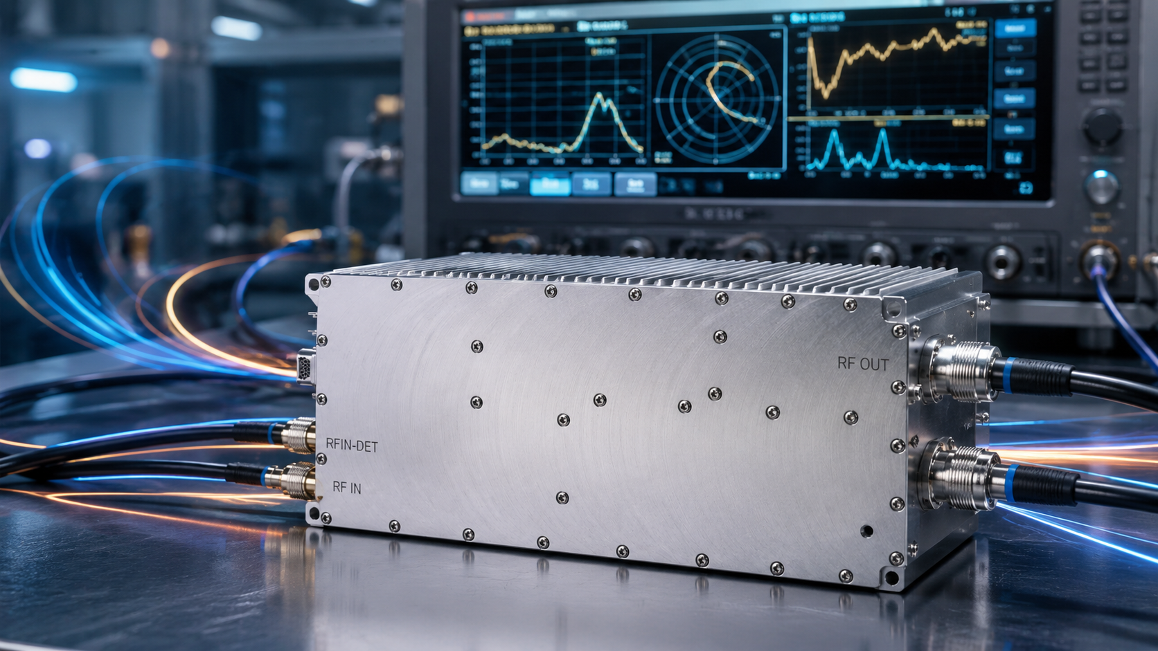
It requires only milliseconds of incorrect bias sequencing for a GaN transistor inside an R&D test bench environment causing expensive hardware destruction. Implementing rigorous hardware-level push-talk gating alongside synchronized direct-current supply limits prevents catastrophic thermal events. Drawing from twenty years evaluating microwave power modules, analyzing failure mechanisms provides a mandatory roadmap protecting high-power setups.
1. What Triggers Instantaneous Burnout in R&D Test Benches?
The Mechanics of Power Sequencing Failure
Engineers operating vector network analyzers frequently encounter abrupt signal loss during high-power sweeps. What’s the real story? Applying radio-frequency excitation before establishing proper drain-to-source bias voltage across gallium nitride transistors induces immediate channel saturation. High reverse currents flow uncontrolled across semiconductor substrate layers causing massive internal damage. This specific condition generates instantaneous localized heating far exceeding maximum component junction temperature ratings. We routinely observe fractured dies under scanning electron microscopes following such catastrophic events during laboratory analysis. Manual laboratory setups often rely on basic toggle switches managing thirty-six-volt direct-current supplies casually. Human operators cannot match required microsecond-level timing tolerances manually under any testing circumstances. Operating testing rigs demands absolute synchronization between signal generators and main current buses constantly. Failure guarantees itself when protocols rely solely on human reaction times during complex measurements. The physics governing compound semiconductors dictate strict adherence regarding charge carrier injection profiles. Overlooking these fundamental material limits destroys expensive hardware within mere milliseconds.
VNA and Spectrum Analyzer Interaction Anomalies
Vector network analyzers output continuous-wave signals dynamically based on defined port configurations continually. Test engineers might inadvertently leave active tracking generators running while cycling main direct-current buses. But here’s the kicker… That rogue milliwatt-level input acts as a massive overdrive stimulus when gate bias voltages remain floating. Active amplification devices suddenly attempt processing continuous-wave tones without sufficient standing-current stabilization present. Reflected energy from poorly matched loads exacerbates localized stress points within internal matching networks severely. Spectrum analyzers exhibit similar behaviors during wideband noise floor evaluations across varying frequency spans. Wideband testing introduces multi-tone intermodulation products straining amplifier linearity past theoretical design limits. An unpowered module receiving complex waveforms suffers immediate diode junction breakdown almost instantly. This interaction demonstrates why leaving test equipment running continuously poses massive risks regarding connected amplifier lifespans. Engineers must terminate all active stimulus generation before adjusting physical power connections.
Human Error in Manual Test Bench Operations
Laboratory environments encourage rapid prototyping requiring frequent connection changes across multiple device iterations. Technicians swap N-female coaxial cables while leaving signal generators enabled out of pure convenience. Removing loads during active transmission reflects total incident power back toward active components instantly. Transient voltage spikes easily exceed specified maximum breakdown thresholds ruining sensitive semiconductor structures. Integrating automated sequencing scripts within testing software mitigates operator-induced errors dramatically across testing cycles. Hardware-level interlocks provide a required fail-safe layer preventing human mistakes from destroying expensive equipment. Relying on paper checklists simply invites disaster when fatigue sets in during long prototyping sessions. Developing rigorous automated gating routines removes arbitrary human timing variables from your critical path entirely. You avoid replacing burnt modules by forcing hardware controllers managing state transitions automatically.
| Failure Mechanism | Trigger Condition | Component Impact | Observation Method |
| Unbiased RF Injection | Excitation applied before VCC | Catastrophic die fracture | Electron microscopy |
| Load Disconnection | Cable removal during transmission | Extreme VSWR reflection | Forward power telemetry |
| Floating Gate Bias | Improper PTT pin grounding | Uncontrolled current draw | Ammeter surge |
| Multi-tone Overdrive | Wideband stimulus unpowered | Junction barrier breakdown | VNA trace collapse |
2. Why Do General-Purpose Solutions Fail Protect GaN Amplifiers?
The Inadequacy of Standard DC Power Supplies
Commercial direct-current units utilize large output filter capacitors causing slow voltage ramp-up profiles. This is where it gets interesting A sluggish voltage rise allows radio-frequency signals an opportunity creating interaction during unstable intermediate bias states. Transistors operating in partial-depletion regions exhibit wild impedance fluctuations constantly. Matching networks designed assuming fifty ohms nominal suddenly face highly reactive loads unexpectedly. This internal mismatch generates severe standing waves entirely contained within module boundaries. External measurement instruments remain blind regarding these internal reflective stresses entirely. High-electron-mobility transistors demand instantaneous current availability exceeding standard supply capabilities regularly. Sourcing cheap power supplies guarantees premature amplifier failure during intensive test regimens. Utilizing specialized laboratory supplies featuring programmable slew rates mitigates these specific transient mismatch scenarios. Engineering teams save money long-term by investing upfront in capable voltage sourcing equipment.
RF Overdrive Under Unbiased Conditions
Many commercial off-the-shelf test benches lack dedicated push-talk gating interfaces completely. General-purpose amplifiers rely entirely on continuous bias applications wasting massive amounts of energy as heat. Dissipating standing currents degrades long-term reliability inside poorly ventilated laboratory racks quickly. Applying a zero dBm input signal during a powered-down state acts identically like an electrostatic discharge event. The internal gate structure lacks protective depletion zones without nominal voltage applications. Charge accumulation rapidly punctures fragile oxide layers separating transistor terminals causing permanent shorts. Devices left unbiased cannot dissipate absorbed radio-frequency energy through normal thermal pathways. You must treat unpowered amplifiers exactly like sensitive static-prone microchips during handling. Shielding inputs using switched attenuators provides an excellent physical barrier against stray signal injection.
Thermal Runaway and Breakdown Voltage Constraints
Gallium nitride provides remarkable power density compared against legacy silicon technologies clearly. This density concentrates massive thermal loads into microscopic physical areas rapidly. General testing solutions rarely incorporate integrated temperature telemetry measuring die-level heating accurately. A cooling fan failure forces heat back down through copper flanges into semiconductor junctions. Lacking immediate thermal shutdown routines guarantees device destruction within milliseconds unconditionally. A dedicated monitoring interface outputting precise millivolt readings proportional against thermal mass becomes mandatory. Generic laboratory amplifiers simply burn out silently without broadcasting preliminary warning metrics beforehand. Active monitoring systems track thermal gradients plotting potential failure trajectories before critical thresholds arrive. Engineers need these analog telemetry feeds driving emergency power cutoffs during sustained testing. Relying strictly on passive external heatsinks proves insufficient when ambient laboratory temperatures fluctuate.
| Parameter | General Purpose Solution | GaN Specific Requirement | Failure Risk |
| Voltage Ramp | >50 milliseconds | <1 millisecond | Internal mismatch |
| Bias Control | Continuous operation | Pin-actuated gating | Thermal fatigue |
| Heat Dissipation | Passive chassis | Active forced-air | Runaway destruction |
| Telemetry | None | Analog voltage output | Blind operation |
3. How Does Timing Misalignment Degrade Measurement Accuracy?
Calibration Shift During VNA Sweeps
Vector network analyzers require precise baseline calibrations establishing reference planes properly. Injecting signals into improperly sequenced amplifiers alters load characteristics dynamically across time. Ready for that good part? This dynamic impedance shift ruins calibration integrity across sweeping frequency bands completely. Measurement traces display distinct ripples indicating unstable reflective conditions rather than actual device performance. Engineers waste hours troubleshooting supposed antenna mismatches when sequencing faults remain true culprits. Proper characterization demands rock-solid stability from all components positioned between instrumentation ports. Any transient behavior introduces mathematical errors into scattering parameter calculations ruining data sets. Validating active device performance requires holding all external variables absolutely constant throughout testing. Eliminating bias-induced impedance wandering guarantees your plotted curves reflect genuine hardware capabilities.
Baseband Noise Floor Surges
Activating radio-frequency generation before establishing stable main voltage rails injects massive baseband noise. Spectrum analyzers capture these transient spikes as broadband interference polluting fundamental measurements heavily. A delayed power supply settling time forces devices operating un-bypassed near saturation levels. Harmonic distortion products multiply exponentially under these starved-current operating regimes polluting spectrums. Spurious emissions exceeding minus sixty decibels relative carrier mask desired low-level signals entirely. Precise timing control guarantees clean signal amplification conforming strictly within specified harmonic boundaries. Characterizing low-noise receivers becomes impossible when your drive amplifier generates excessive broadband trash. Controlling the startup sequence keeps unwanted spurious tones suppressed below detectable thresholds. Your laboratory instruments remain capable mapping clean spectral responses avoiding false positive readings.
Transient Reflections and Mismatch Penalties
Connecting test fixtures demands perfect fifty-ohm environments maintaining power transfer efficiencies efficiently. Misaligned start-up sequences cause momentary short-circuit behaviors at input terminals causing severe reflections. Signal generators facing instantaneous total reflection risk internal component damage themselves eventually. We frequently diagnose damaged tracking generator outputs directly resulting from poorly timed external amplifiers. A cascading failure scenario develops destroying multiple costly laboratory instruments simultaneously across benches. Maintaining an input voltage standing wave ratio below one point six remains impossible during sequencing faults. Hardware isolation using high-isolation switches prevents reflected energy from reaching sensitive upstream sources. Protecting your primary signal generators saves thousands replacing blown output attenuator blocks. Every test bench requires strict isolation protocols governing forward energy flow paths exclusively.
| Timing Anomaly | Measurement Instrument | Direct Consequence | Data Impact |
| Delayed VCC | Vector Network Analyzer | Impedance fluctuation | Corrupted S-parameters |
| Early RF Stimulus | Spectrum Analyzer | Baseband noise surge | Obscured spurious tones |
| Asynchronous Gating | Power Meter | Power transient spike | Inaccurate yield analysis |
| Unstable Bias | Oscilloscope | Waveform clipping | Missed peak voltages |
4. What Are Core Architecture Requirements For High-Power Test Rigs?
Hardware-Level PTT Pin Sequencing
Designing robust testing architectures requires shifting control away from human operators toward deterministic hardware. What’s the real story? A dedicated push-talk line operating on standard three-point-three volt logic offers nanosecond-level responsiveness. Grounding this pin forces total amplifier shutdown regardless of input stimulus presence instantly. System controllers must execute programmed logic driving main power buses active before enabling gate logic. This definitive operational order eliminates arbitrary failure windows completely securing your investment. Software delays prove insufficient because operating system interrupts cause unpredictable timing jitter constantly. Hardware interlocks remain absolute foolproof methodologies protecting fragile semiconductor junctions from user error. Relying on precision microcontrollers managing state machines provides guaranteed timing relationships between power rails. Engineering teams scaling automated testing must mandate physical gating lines across all active fixtures.
VSWR and Load Pull Limitations
Evaluating antenna arrays requires pushing amplifiers into severe impedance mismatches intentionally testing limits. Laboratory environments utilize load pull tuners analyzing non-linear transistor behaviors under extreme stress. An architecture lacking embedded reflective power telemetry operates blindly during these destructive evaluations. Real-time reverse detection voltage outputs allow supervisory controllers a mechanism executing rapid shutdowns. Exceeding established tolerance thresholds triggers automated disengagement before thermal limits reach critical mass. Robust designs incorporate ruggedized output circulators mitigating reflection energy naturally absorbing standing waves. Pushing one hundred watts into a short circuit demands immediate protection circuitry intervention. Your system software reads reverse power telemetry continuously making millisecond decisions regarding safety. Building custom load pull stations demands amplifiers capable surviving momentary infinite reflection states.
Integration of Active Monitoring Interfaces
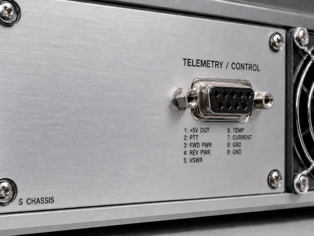
Data acquisition systems demand continuous analog telemetry streams detailing amplifier health metrics continuously. A standardized DB9 connector provides centralized access monitoring forward power levels simultaneously. Temperature detection voltages offer predictive maintenance capabilities identifying degraded cooling fan performance early. Relying solely upon RS485 serial communication introduces unacceptable latency during catastrophic fault events. Analog voltage lines provide instantaneous feedback necessary supporting millisecond reaction times protecting assets. Architecture designs must process these analog signals using dedicated field-programmable gate arrays. Sending raw millivolt readings directly into fast analog-to-digital converters ensures zero processing lag. Systems engineers build robust protective envelopes monitoring every critical operational parameter dynamically. These hardware interfaces prevent single-point failures cascading across expensive laboratory instrumentation racks.
| Interface Signal | Connector Pin | Voltage Range | Action Required |
| PTT Control | DB9 Pin 3 | 0V to 3.3V | Enable RF gating |
| Forward Monitor | DB9 Pin 6 | Analog millivolts | Calculate output watts |
| Reverse Monitor | DB9 Pin 7 | Analog millivolts | Monitor VSWR stress |
| Temp Monitor | DB9 Pin 8 | Analog millivolts | Trigger cooling loop |
5. How CRF-PA-20M1000M-100W Solves Power Sequencing Dilemmas?
Advanced GaN Technology with Built-in PTT Control
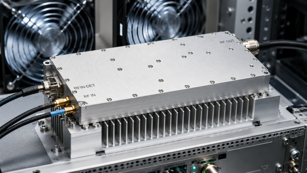
CorelixRF engineers developed specific mitigation strategies addressing laboratory-environment failure modes directly through hardware. But here’s the kicker This CRF-PA-20M1000M-100W utilizes advanced gallium nitride die structures hardened against transient input spikes. Utilizing DB9 Pin 3 allows logic-level gating separating physical voltage application from RF readiness. A testing rig controller applies nominal thirty-six volts directly through robust 2W2 connectors safely. Applying zero volts along Pin 3 keeps active stages completely isolated rejecting rogue continuous-wave signals. Asserting three-point-three volts completes this sequence engaging active amplification precisely when required deterministically. This architecture explicitly solves timing mismatch scenarios by physically blocking transistor channel conduction. You gain absolute control managing state transitions using simple transistor-transistor logic signaling. Testing setups remain protected even if signal generators run continuously during cable swaps.
Real-Time Telemetry via DB9 and RS485 Interfaces
Diagnostic visibility represents a mandatory requirement characterizing microwave performance accurately across widebands. CorelixRF provides granular access managing internal states using a detailed DB9 monitoring port. Pin 4 accepts variable direct-current voltages adjusting total system gain seamlessly across twenty decibels. This attenuation control prevents driving delicate measurement instruments past absolute maximum input ratings unexpectedly. Serial communications operating over RS485 protocols allow automated test software integration gathering historical trend data. Pin 5 provides continuous input detection voltage guaranteeing stimulus levels remain within zero dBm boundaries. Reading forward and reverse voltages simultaneously gives test engineers an exact reflection coefficient calculation instantly. Tracking internal temperatures prevents degrading module lifespan during long-duration burn-in testing cycles. Accessing raw analog data gives your control system ultimate authority managing protective limits.
Complete Fault Protection for Overdrive and VSWR
Surviving abusive laboratory testing demands multiple layers protecting internal active components from severe damage. This module features built-in protection routines addressing over-voltage transients automatically stopping destructive currents. Exceeding nominal operating temperatures triggers internal disconnect mechanisms utilizing forced-air cooling paths heavily. Heavy external heatsinks attached securely guarantee continuous one-hundred-watt output across broadband frequencies stretching twenty megahertz upward. An input voltage standing wave ratio maintained strictly around one point six guarantees source stability. Spurious emissions remaining below minus sixty decibels keep sensitive nearby receivers operating quietly. We guarantee performance stability providing factory test data reviewing project specifications beforehand. Integrating this ruggedized block into your rack eliminates constantly replacing cheaper burnt-out alternatives. You achieve reliable continuous-wave amplification spanning massive frequency ranges without sacrificing equipment safety.
| Specification | CRF-PA-20M1000M-100W Value | Engineering Benefit |
| Operating Frequency | 20 – 1,000 MHz | Broadband testing coverage |
| Rated Output Power | 100 Watts | High-stress component evaluation |
| Spurious Emissions | -60 dBc | Clean baseband test floors |
| Gain Flatness | +/- 4 dB | Predictable VNA calibrations |
Managing proper timing sequences between radio-frequency excitation and direct-current supply buses prevents catastrophic hardware failures. Implementing robust telemetry utilizing dedicated analog monitoring pins guarantees continuous operational visibility during extreme testing procedures. System integrators requiring resilient broadband power modules must evaluate advanced gallium nitride architectures thoroughly. Contact CorelixRF engineering support requesting detailed installation documentation outlining CRF-PA-20M1000M-100W integration specifics today.
- Q1: What is the required power supply voltage for the CRF-PA-20M1000M-100W module?This unit requires a nominal direct-current supply operating at thirty-six volts connected via standard 2W2 interfaces.
- Q2: How does the PTT control pin operate during sequencing?Applying three-point-three volts engages active transmission stages while zero volts forces complete amplifier shutdown preventing overdrive faults.
- Q3: What interfaces manage internal telemetry reporting?A standard DB9 connector provides analog voltage outputs monitoring forward power levels alongside an RS485 digital serial bus.
- Q4: How does this module handle extreme thermal loads?Built-in temperature protection routines operate alongside heavy external heatsinks requiring active forced-air cooling methods maintaining stability.
- Q5: What is the maximum acceptable input stimulus level?This system demands input signals remaining at zero decibel-milliwatts guaranteeing linear operation without risking semiconductor junction damage.
Make the lab setup and report curves part of the RFQ
Test-bench issues become easier to resolve when the RFQ lists signal source, cable loss, load condition, calibration setup, power sequencing, gain flatness, spurious limits and report format.
Recommended next step: send the operating band, output power target, duty cycle, load condition, control interface, protection or thermal limits and required FAT documents. CorelixRF can review this How to Avoid Test Bench Failures with Proper RF Power Sequencing? requirement against standard RF amplifier platforms, RF front-end options and controlled customization paths.