
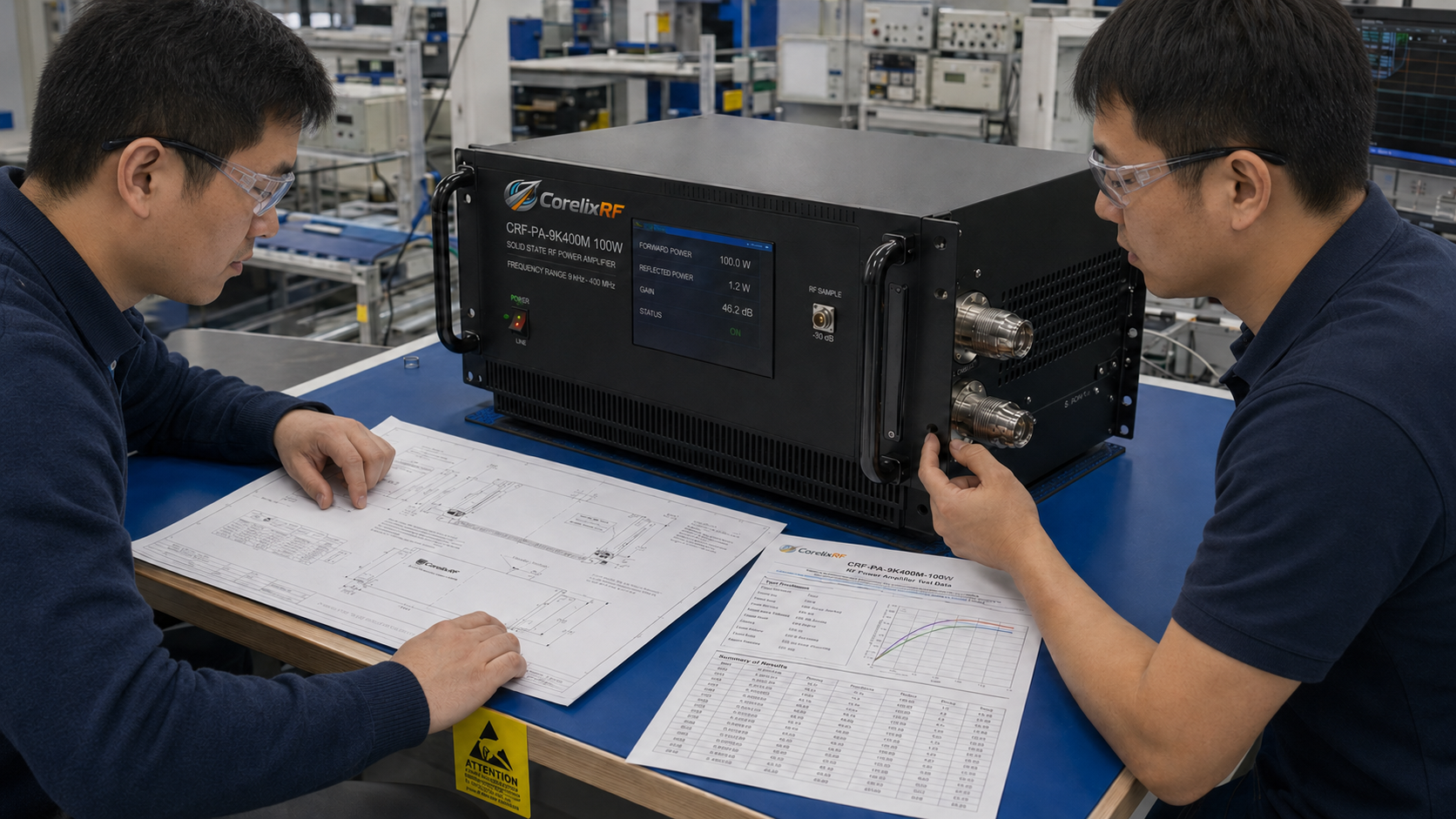
RF power amplifier procurement often stalls at final stages because quality departments lack rigorous testing protocols. Relying on generalized datasheets leaves systems vulnerable, resulting in costly acceptance failures and delayed after-sales resolutions. Here is the deal: implementing strict Factory Acceptance Testing (FAT) alongside Site Acceptance Testing (SAT) protects your investment by verifying physical mechanisms before deployment. With 30 years of RF hardware manufacturing experience, CorelixRF relies strictly on measured laboratory data rather than promotional claims. Writing precise acceptance criteria forces suppliers into delivering objective engineering truth, ensuring hardware performs exactly as specified within your critical communication or electronic warfare networks.
1. What Are the Core Differences Between FAT and SAT in RF Projects?
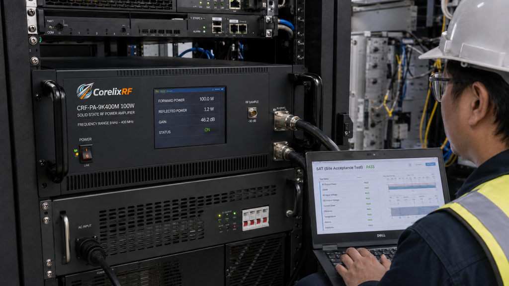
Understanding where specific tests occur prevents major logistical headaches down the road. What’s the real story? FAT occurs exclusively at the manufacturing facility before equipment ships. This phase verifies baseline performance under highly controlled laboratory conditions. We test units using a standard 50 Ω system. Engineers supply a rated AC input. Ambient temperatures remain stable. SAT happens at your installation site. This phase evaluates how hardware handles real-world variables like fluctuating mains power, imperfect antenna connections, and local thermal environments. A unit passing FAT might fail SAT if facility environmental controls fall short. Therefore, your quality department must document both phases distinctly. FAT proves the manufacturer built the product correctly. SAT proves the product functions properly within your specific operational ecosystem. Combining these two distinct evaluation layers creates an impenetrable shield against sub-standard hardware deliveries.
Acceptance Testing Phases
| Phase | Location | Primary Objective | Environment |
| FAT | Factory | Verify baseline specifications | Controlled 50 Ω system |
| SAT | Client Site | Verify system integration | Real-world variables |
| Commissioning | Client Site | Final operational handover | Active deployment |
2. How Do You Define Sample Clauses for a 100W Wideband Amplifier?
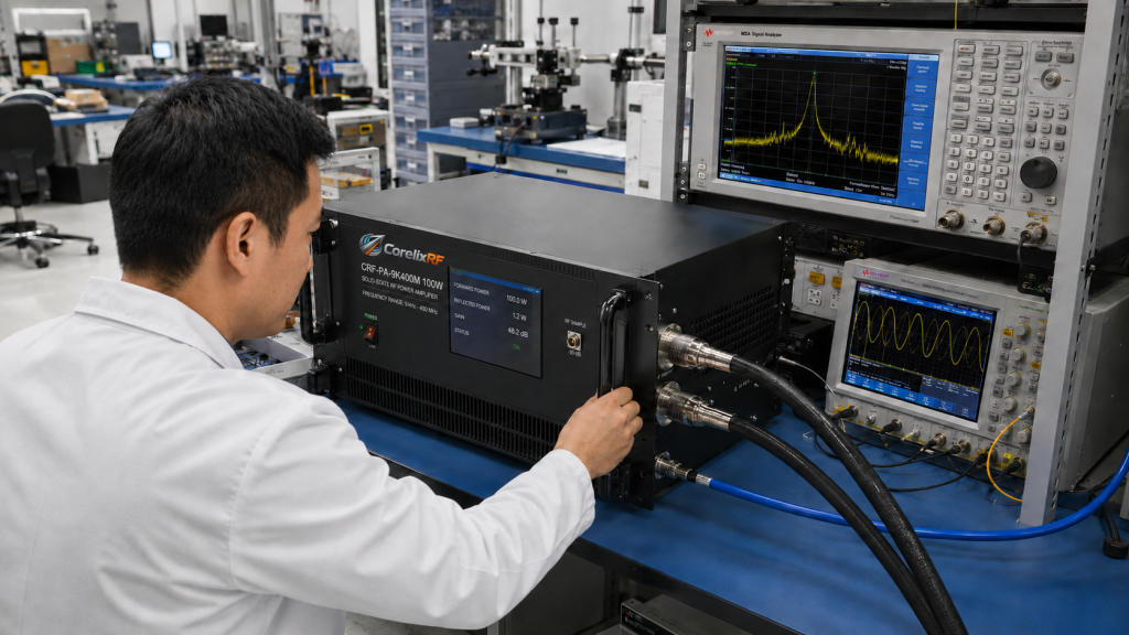
Writing exact criteria prevents misunderstandings during delivery. This is where it gets interesting Quality teams must specify absolute parameters rather than accepting vague operational ranges. Take our CRF-PA-9K400M-100W model as an example. This solid-state RF power amplifier operates over a frequency range spanning 9 kHz up through 400 MHz. We guarantee a 100 W minimum output power, alongside a 150 W typical rating. Your FAT document must require verification of these exact figures. Furthermore, inspectors should mandate testing the 50 dB minimum small-signal gain. Flatness must remain within a tight -3 dB through +3 dB window. P1dB compression point measurements must hit 80 W. Including these specific data points within your procurement contracts forces suppliers into delivering objective evidence. If physical units fail these laboratory benchmarks, rejection becomes automatic. Such rigor eliminates subjective arguments regarding acceptable performance degradation.
CRF-PA-9K400M-100W Baseline Criteria
| Parameter | Minimum | Typical | Maximum |
| Frequency Range | 9 kHz | – | 400 MHz |
| Output Power | 100 W | 150 W | – |
| Small-Signal Gain | 50 dB | – | – |
| P1dB | – | 80 W | – |
3. Why Do Impedance Mismatch and Gain Drift Cause Acceptance Failures?
System integration introduces complex physics variables which laboratory environments rarely replicate perfectly. But here’s the kicker A functional module might burn out immediately upon field deployment if engineers ignore reflected power mechanics. CorelixRF mandates a 100% frequency match between our amplifiers and your antennas; simple band overlap guarantees nothing but hardware failure. When mismatch occurs, energy reflects backward into the amplification stages. High VSWR conditions generate extreme thermal stress across transistor junctions. We engineer the CRF-PA-9K400M-100W with built-in VSWR protection and alarm functions. It handles an input impedance characterized by a 2.0:1 maximum VSWR. However, relying solely upon protective circuits degrades long-term reliability. SAT protocols must measure forward power against reverse power under actual installation conditions. Optional forward/reverse power monitoring configurations exist precisely for this diagnostic purpose. Documenting thermal stability during these field tests prevents warranty disputes.
Common SAT Failure Mechanisms
| Failure Mode | Physical Cause | Prevention Strategy |
| Thermal Shutdown | Excessive VSWR reflection | 100% frequency matching |
| Gain Compression | Inadequate cooling airflow | Measure ambient temperature |
| Transistor Burnout | Over-drive condition | Implement input power limits |
4. How Can Quality Departments Avoid Disputes During Final Testing?
Ambiguity remains the enemy of efficient procurement. You might be wondering Buyers often accept unverified claims instead of demanding raw laboratory evidence. We provide comprehensive mechanical drawings, test data, alongside control protocols for project review. This transparency ensures your mechanical engineers know exactly how a 28 kg, 19-inch 4U rack-mount chassis integrates into your racks. Our equipment utilizes air cooling while drawing approximately 700 W typical power. Your FAT should confirm these mechanical realities before shipping occurs. Furthermore, systems include over-temperature, over-current, and over-voltage protection. Inspectors must intentionally trigger these fault states during factory visits. Verifying alarm functionality proves the hardware can survive hostile electronic warfare or aerospace control environments. We manufacture units under an ISO 9001 quality management system. Requesting this documentation upfront establishes a baseline for acceptable manufacturing standards.
Built-In Protection Verification
| Protection Type | Test Method | Expected Result |
| Over-temperature | Restrict cooling airflow | System alarm and shutdown |
| Over-current | Induce load fault | Current limiting activation |
| VSWR | Connect mismatched load | Reflected power alarm |
5. What Are the Required Steps to Execute a Flawless Acceptance Protocol?
Structuring a robust evaluation requires discipline and standardized checklists. Ready for the good part? Your technical team should initiate a 48-hour engineering review immediately upon receiving our proposed specifications. Compare your target waveform type, duty cycle, alongside environmental constraints against our quoted capabilities. Once verified, draft a FAT document detailing harmonic requirements, such as verifying -15 dBc at 100 W. Spurious emissions must sit below -60 dBc. Define the control interface testing methodology, utilizing either RS485 or LAN connections. During SAT, repeat baseline performance checks using site-specific AC power, ensuring 220 V ±10% tolerances. Check N-Female RF connector integrity after transit. If project-specific regulatory documentation was requested, verify its accuracy against delivered hardware. Executing these steps systematically removes emotion from B2B purchasing decisions.
Engineering Review Checklist
| Verification Item | Target Specification | Document Source |
| Harmonics | -15 dBc @ 100 W | Lab Scan |
| Spurious | -60 dBc | Lab Scan |
| Power Supply | AC 220 V ±10%, 50/60 Hz | Site Audit |
| Connectors | N-Female In/Out | Visual Inspection |
Conclusion
Proper acceptance testing separates successful system integration from catastrophic project failures. Defining strict FAT and SAT parameters based on measurable physics ensures your RF power amplifiers perform reliably under duress. Require comprehensive lab data, verify protective circuits, and mandate 100% frequency matching. Do not leave your quality assurance to chance. Contact our engineering team today to receive a complete FAT/SAT document template tailored for your next wideband amplifier procurement project.
FAQ Section
Q1: What is FAT in RF amplifier procurement?
Factory Acceptance Testing (FAT) involves verifying the physical and electrical specifications of an amplifier, such as the CRF-PA-9K400M-100W, at the manufacturer’s facility under controlled 50 Ω system conditions before shipping.
Q2: How does VSWR protection work?
VSWR protection mechanisms monitor reflected power caused by impedance mismatches. If reverse energy exceeds safe thresholds, the amplifier triggers an alarm and reduces or cuts output power to prevent internal transistor damage.
Q3: Why is P1dB an essential measurement during testing?
The 1 dB compression point (P1dB) indicates the absolute maximum linear output power capability. Verifying an 80 W P1dB ensures the amplifier will not distort complex waveforms before reaching its saturated output limit.
Q4: What should site acceptance testing (SAT) cover?
SAT should replicate baseline FAT tests but introduce site-specific variables like local AC power stability, actual antenna load impedance, and rack ambient temperatures to ensure realistic operational reliability.
Q5: How do I initiate a technical review with CorelixRF?
Provide your target frequency range, output power, waveform type, CW or pulse operation, duty cycle, control interface, mechanical constraints, and environmental requirements to trigger our 48-hour engineering review.
Turn acceptance criteria into a factory-verifiable RFQ
Acceptance criteria should be measurable: frequency points, output power, gain flatness, harmonics, spurious limits, VSWR protection behavior, thermal soak time, control interface and report format. This makes quotation, FAT and delivery approval much cleaner.
Recommended next step: send the target band, output power, duty cycle, load condition, control interface, cooling limit and required FAT documents. CorelixRF can map this RF power amplifier acceptance criteria requirement to a standard platform or a controlled customization path.