
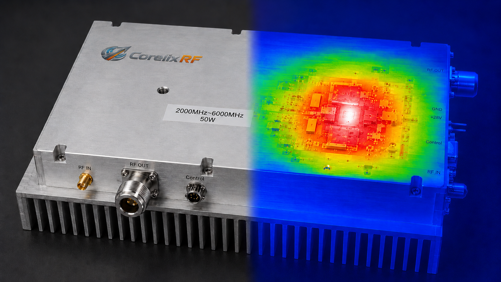
When procuring and integrating high-power radio frequency power amplifiers (RF PAs), system engineers and procurement personnel frequently make a fatal error: relying solely on nominal output power and operating temperature ranges from the datasheet to make decisions. However, the nominal 100 W CW (Continuous Wave) listed on a datasheet represents a static parameter under ideal conditions. If the amplifier operates continuously at full load for 30 minutes in an actual system, the internal thermal dissipation state will directly determine the success or failure of the project.
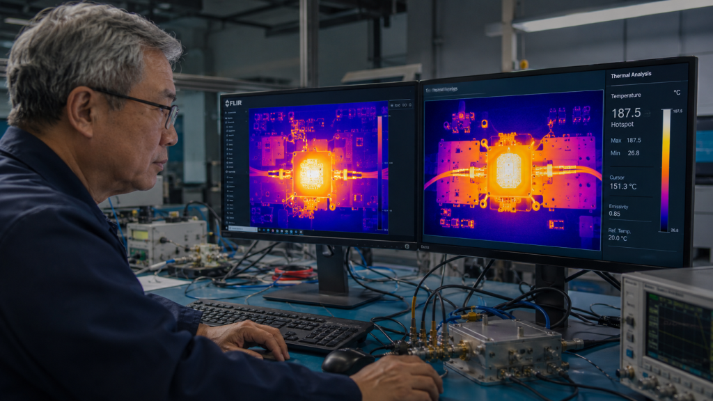
Thermal failure serves as the primary cause of RF system crashes. Engineers face the risk of blind integration if they lack direct measurements of the internal thermal distribution within the amplifier. Standardized test reports must include thermal imaging maps, serving as credible physical evidence for evaluating thermal design reliability and system-level heat dissipation strategies.
Thermal Failure Risks: The Physical Truth in Engineering
Within solid-state RF power amplifiers (SSPAs), GaN (Gallium Nitride) transistors operate at extremely high power densities. No power amplifier can achieve a 100% DC-to-RF conversion efficiency. Unconverted DC power transforms entirely into thermal energy during actual engineering practice.
When the amplifier operates in a high-power output state, the junction temperature (Tj) will surge rapidly if the cooling system fails to conduct heat effectively from the GaN die to the external heat sink. Excessive junction temperatures trigger a series of cascading physical degradation mechanisms:
- Gain Drift: Transistor transconductance decreases as temperature rises, causing output power compression and reduced gain.
- Impedance Mismatch: Thermal expansion and the temperature dependence of the dielectric constant cause the Voltage Standing Wave Ratio (VSWR) of the microwave circuit to deteriorate. Thermal drift directly destroys system compatibility between the antenna and the amplifier for RF systems requiring perfect matching across the entire frequency band.
- Irreversible Device Damage: Operating continuously at extreme junction temperatures accelerates metallization electromigration, drastically reducing the Mean Time Between Failures (MTBF) of the power amplifier.
How to Read Thermal Images: Core Acceptance Standards for High-Power RF PAs
Inside the CorelixRF laboratory, we reject any guesswork regarding thermal stability, basing everything entirely on measured physical data. Thermal imaging maps visually demonstrate the true temperature gradient distribution of the amplifier under extreme RF loads. Technicians should focus heavily on the following dimensions when accepting and reading thermal imaging test evidence:
1. Peak Temperatures and Hotspots of Core Components Consider the CRF-PA-2000M6000M-100W broadband amplifier module as an example, which delivers 100 W of rated CW output power across the 2000–6000 MHz frequency band, powered by a +28 V nominal voltage. The GaN package flange will display the highest temperature (hotspot) under the thermal imager. Acceptance standards must ensure that the peak temperature of this hotspot maintains a sufficient engineering derating margin from the absolute maximum rated junction temperature of the device under maximum power dissipation states.
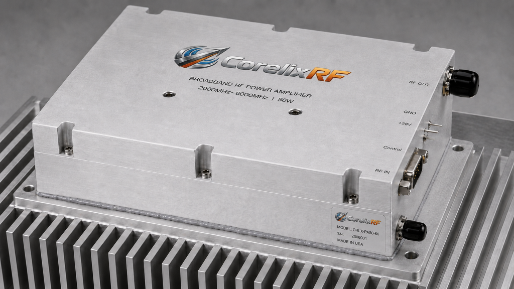
2. Uniformity of Thermal Gradients Thermal imaging examines the uniformity of heat distribution alongside peak temperatures. The temperature gradient across the RF PCB must remain relatively flat for the CRF-PA-2000M6000M-100W module, which must support up to 200 MHz instantaneous bandwidth and maintain a small-signal gain between 41–51 dB. If the thermal image reveals localized heat accumulation while the surrounding substrate remains extremely cold, this typically indicates process defects such as voids in the Thermal Interface Material (TIM) or poor soldering, obstructing the heat conduction path.
3. Thermal Response Under Extreme Conditions
Credible thermal imaging tests should not occur solely under perfect 50-ohm matching. Thermal dissipation increases instantaneously when a severe mismatch occurs in the system, causing reflected power to return inside the amplifier. The thermal map records how heat impacts the final stage power transistors under such conditions.
CorelixRF Empirical Evidence and System-Level Heat Dissipation Recommendations
The survivability of a single module depends heavily on comprehensive system-level planning when evaluating high-power RF hardware. All high-power modules from CorelixRF undergo rigorous full-load thermal testing prior to shipment, providing customers with transparent test conditions and empirical evidence.
We propose the following thermal design recommendations to ensure the equipment maintains high reliability in harsh environments (such as storage from -55°C to +85°C and extreme operating conditions):
- An External Heat Sink is Mandatory: High-power modules like the CRF-PA-2000M6000M-100W cannot sustain long-term continuous wave operation relying solely on their 200×158×25 mm mechanical enclosure. Customers must configure an external cold plate or an air/liquid cooling heat sink equipped with sufficient heat dissipation area.
- Focus on the Mounting Interface: High thermal conductivity silicone grease or phase change materials must be applied between the module baseplate and the system heat sink. The surface roughness and flatness must meet machining specifications to minimize contact thermal resistance.
- Integrate Hardware Protection Mechanisms: We strongly advise customers to enable monitoring functions within their control systems. For instance, utilize the D-Sub 15-Pin control interface or the optional M1 RS485 version to read internal analog temperature reports in real time, coordinating this data with voltage, current, and VSWR protection logic. The hardware must immediately trigger an alarm or disable the PA enable function (PA_EN) to protect the core RF link the moment the external cooling system fails and temperatures approach critical thresholds.
Next Steps: Schedule an Engineering Review to Eliminate System Risks
Procurement decisions cannot rely on vague promotional slogans within the B2B high-tech manufacturing industry. You need concrete laboratory data, detailed thermal design specifications, and rapid technical responses if you are seeking highly reliable RF power amplifiers for radar, electronic warfare, or broadband communication systems.
Avoid late-stage system-level thermal crashes caused by blind component selection. Contact CorelixRF armed with your available system cooling volume, environmental temperature constraints, and RF link requirements.
[Schedule a 48-Hour Engineering Review]
We will conduct a comprehensive calculation of frequency matching, gain requirements, and heat dissipation capabilities based on your specific application scenarios. We will supply a genuine test data package (including thermal imaging evidence) to support your procurement and quality acceptance processes.
Turn this RF requirement into a quotable specification
Use this article as a starting point for a buildable RF specification. Before quoting, CorelixRF normally checks frequency range, output power, gain flatness, duty cycle, load mismatch, thermal path, control interface, enclosure limits and acceptance data.
- thermal reliability articles – continue with related thermal drift, cooling and sealed-enclosure reliability notes
- RF power amplifier platforms – match the article topic to available RF power amplifier families
- solid state power amplifier page – review SSPA architecture when reliability and repeatable test data matter
- RFQ checklist – send the data buyers usually forget, including band, power, duty cycle, interface and test standard
- delivery documentation – check what documents can support incoming inspection, FAT review and long-term maintenance
- case studies – review similar engineering paths before sending an RFQ
- engineering contact – send the application notes, block diagram or target specification to engineering sales
For a faster review, send operating band, power target, modulation or waveform, antenna/load condition, cooling limit, mechanical envelope and target test standard through the RFQ or contact path.