
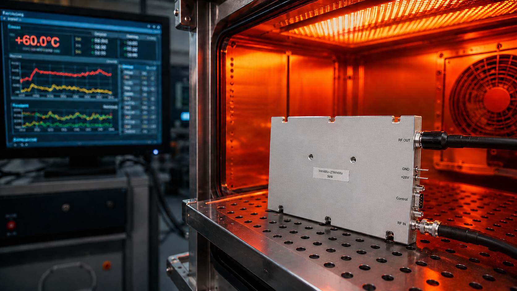
Project managers face severe reliability risks during final system deployments constantly. Many assemblies pass basic laboratory evaluations perfectly under room temperature conditions. Sustained full-power transmission causes catastrophic hardware failures later. Implementing a rigorous RF power amplifier burn-in test prevents disastrous site acceptance issues. CorelixRF provides undeniable engineering data supporting our industrial-grade delivery standards.
1. Why Do Static Datasheet Parameters Fail During Field Operations?
Understanding Basic Evaluation Limits
You might be wondering. Why do perfectly functional components suddenly degrade on site? System integrators endure massive headaches during final acceptance trials frequently. Initial five-minute evaluations at ambient temperatures show flawless saturation limits. Field deployments across communication base stations tell a completely different story. Hardware modules sustain continuous high-power radio frequency emissions for hours. Communication links drop unexpectedly due entirely toward underlying thermal stress factors. Error rates spike dramatically under heavy operational loads. Certain modules even suffer total physical destruction. Static parameter sheets lack crucial dynamic endurance metrics entirely. Buyers rely heavily upon simplified laboratory numbers wrongly. They ignore dynamic thermal stability under continuous heavy strain. An RF power amplifier burn-in test addresses these hidden vulnerabilities directly. We simulate severe field conditions accurately inside our factory walls. Passing this strict barrier ensures flawless long-term reliability. Engineering professionals require physical proof rather than simple marketing promises.
Static Vs Dynamic Parameters
| Parameter Type | Test Duration | Environmental Condition |
| Static Datasheet | 5 minutes | Room temperature |
| Dynamic Burn-In | 48-72 hours | +60°C operating maximum |
| Field Operation | Continuous | Unpredictable outdoor |
2. How Does Thermal Accumulation Affect Continuous Wave Operations?
Gallium Nitride Physical Degradation
Here’s the deal. Understanding module failure requires examining fundamental semiconductor physics deeply. Gallium nitride solid-state platforms produce significant waste heat continually. High-power wideband signals create massive internal thermal loads quickly. Continuous wave configurations cause rapid internal junction temperature spikes. Charge carrier mobility within semiconductor materials drops heavily. Two severe engineering problems arise immediately from this phenomenon. Gain drift ruins fixed link budget designs completely. A nominal 40 dB capability might degrade rapidly under stress. Your complete transmission equivalent isotropically radiated power falls short. Phase linearity deteriorates significantly alongside rising internal temperatures. Third-order intermodulation distortion worsens under accumulated thermal loads. Spectral emission masks exceed allowable limits completely. We observe these failures repeatedly across average commercial equipment. Proper RF power amplifier burn-in test protocols identify weaknesses early. Factory screening prevents defective units from shipping altogether. Reliability demands rigorous stress management techniques always.
Thermal Degradation Effects
| Physical Effect | System Consequence | Test Detection Method |
| Carrier mobility drop | Gain degradation | Gain drift monitoring |
| IMD3 worsening | SEM failure | Linearity stress check |
| Junction overheating | Component burnout | Continuous wave loading |
3. What Are Core Burn-In Test Protocols For Extreme Temperatures?
High-Temperature Endurance Tracking
This is where it gets interesting. CorelixRF intercepts invisible manufacturing hazards through extreme environmental simulations. We subject our hardware toward severe continuous operational stress. Our CRF-PA-300M2700M-50W module delivers 50 W output power. This unit operates across 300 to 2700 MHz. We place modules inside specialized extreme high-temperature chambers. Equipment runs continuously at +60°C maximum ambient parameters. Units receive nominal +28 V DC supply voltages. Tests last between forty-eight and seventy-two hours straight. Engineers monitor small-signal gain fluctuations continuously. We track performance strictly between 38 and 48 dB. Gain variations must remain within strict engineering tolerances securely. We reject any module showing thermal runaway characteristics. True RF power amplifier burn-in test cycles demand absolute perfection. Long duration assessments expose subtle manufacturing defects predictably. End users receive only thoroughly verified amplification hardware. Our factory testing guarantees continuous high-power reliability globally.
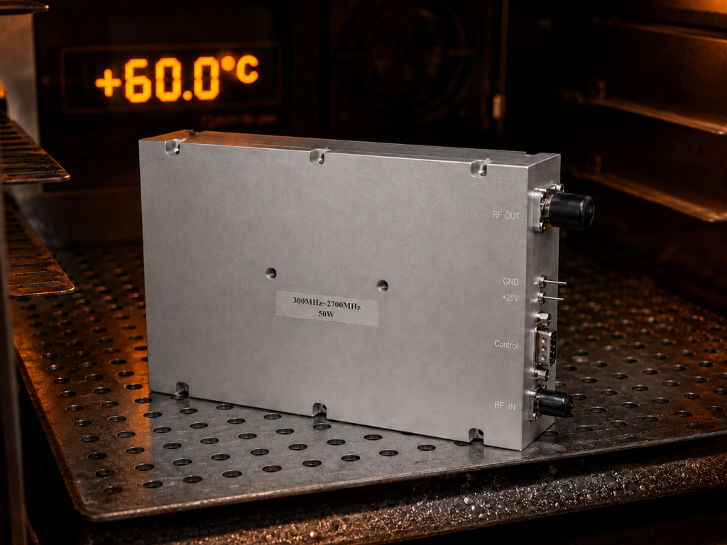
CRF-PA-300M2700M-50W Parameter Constraints
| Parameter | Target Value | Constraint Condition |
| Frequency Range | 300-2700 MHz | Broadband coverage |
| Output Power | 50 W CW | Saturated capability |
| Small-Signal Gain | 38-48 dB | Within +60°C ambient |
4. How Do We Validate VSWR And Impedance Mismatch Tolerance?
Surviving Total Reflection Events
Wait, there’s more. Real field installations present unpredictable physical challenges constantly. Broken radio frequency cables cause massive impedance mismatch issues quickly. Damaged antennas reflect huge amounts of energy backward. Loose SMA-KFD46 connectors generate dangerous standing wave ratios. Massive energy dumps return into your final amplification stage. Our testing platforms introduce intentional full reflection phases. We simulate total open and short circuit conditions deliberately. Industrial-grade hardware must survive these extreme reflection events safely. Internal absorbing circuits cannot fail under continuous heating scenarios. Isolator components must handle intense reflected power securely. A standard RF power amplifier burn-in test includes severe VSWR stress. We verify survival rates across multiple phase angles meticulously. Field installations demand robust defense against accidental physical damage. Our modules withstand severe operational abuses regularly. System integrators deploy our equipment with total confidence.
Field VSWR Risk Factors
| Defect Source | Reflected Energy | System Impact |
| Broken antenna | Extremely high | Complete mismatch |
| Crushed cable | Moderate-High | Partial reflection |
| Loose connector | Variable | Phase shifting stress |
5. What Ensures Protection Logic Reliability During A Fault?
Emergency Shutdown Validation
Ready for the good part? Project acceptance requires safe shutdown capabilities during emergencies absolutely. Modern solid-state devices feature robust automated protection mechanisms. Our units offer critical over-temperature and over-voltage safeguards. We intentionally block external heat sink thermal paths during testing. This forces internal temperatures past predefined safe threshold levels. The CRF-PA-300M2700M-50W shuts down above 80°C±5°C securely. We monitor logic levels across D-Sub 9-pin interfaces. Hardware must cut transmission within a 10 µs window. Fast disable times prevent catastrophic module destruction perfectly. Equipment must automatically recover below 70°C±5°C smoothly. We verify seamless restoration without destructive self-oscillations. An effective RF power amplifier burn-in test validates control logic entirely. Software integration depends upon reliable physical hardware responses. System controllers need precise action times for guaranteed safety. CorelixRF guarantees dependable emergency fault handling continuously.
Hardware Protection Parameters
| Protection Type | Trigger Threshold | Recovery Action |
| Over-Temperature | Above 80°C±5°C | Auto below 70°C±5°C |
| Enable Control | 10 µs max | Seamless restoration |
| Supply Voltage | Exceeds 32 V | Current limitation |
6. How Does CorelixRF Replace Basic Pass Labels With Raw Data?
Automated High-Precision Data Collection
What’s the real story? Simple pass labels mean absolutely nothing for smart procurement professionals. Complete accountability requires transparent engineering data tracking consistently. Our automated systems record detailed operational trajectories continuously. We sample core parameters every five minutes exactly. Real-time consumption current verification spans +24 V through +32 V. Typical operating currents hover around 7.2 A safely. We measure transient outputs across 200 MHz instantaneous bandwidths. Baseplate temperature gradients undergo intense analytical scrutiny constantly. High-precision data collection identifies weak internal transistors effectively. We spot poor manufacturing solder joints before shipping units. Every single delivered module features incredible batch consistency. An RF power amplifier burn-in test must produce actionable data. Guesswork has no place within industrial manufacturing processes today. We provide undeniable facts supporting our quality claims. Clients receive comprehensive mathematical proof demonstrating hardware superiority.
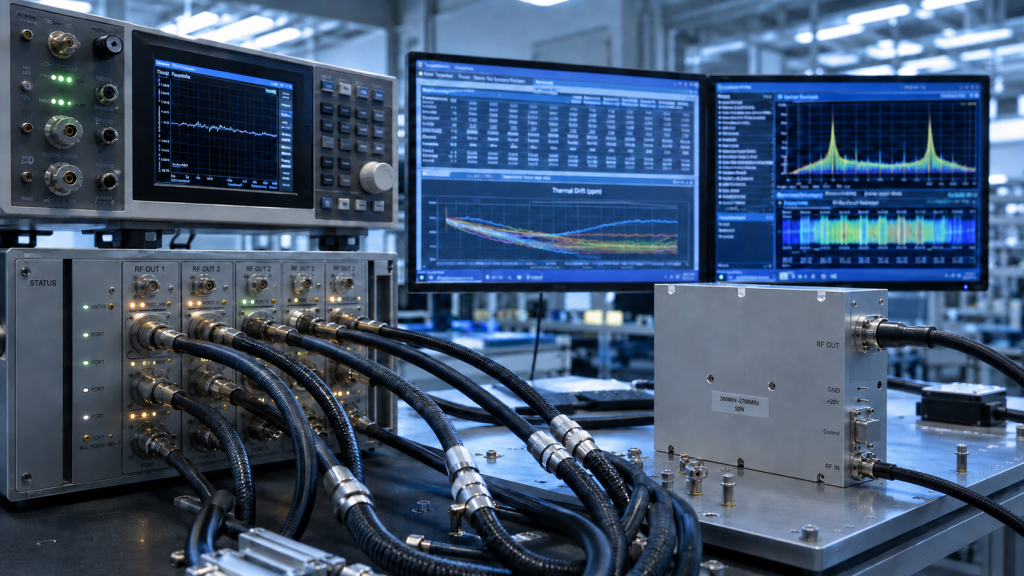
Data Sampling Matrix
| Parameter Recorded | Interval | Verification Goal |
| Operating Current | 5 minutes | Power consumption consistency |
| Transient Power | 5 minutes | Bandwidth flatness check |
| Baseplate Temp | 5 minutes | Thermal gradient tracking |
7. What Specific Factory Acceptance Test Data Should You Request?
Mandating Comprehensive Evidence Packages
Let’s get straight to the point. Overseas integrations carry heavy financial and timeline risks universally. Global system integrators must demand comprehensive evidence packages. A compliant industrial delivery requires specific documented proof continually. Request a detailed factory acceptance test report immediately. Documentation must state ambient temperatures and exact supply voltages clearly. Excitation signal types require precise technical logging. Insist upon continuous load power drift curves without exception. Ask for temperature rise graphs spanning entire operational durations. Secure strict pinout definitions like VDD and PA_EN beforehand. Software debugging requires confirmed protection trigger thresholds absolutely. Complete RF power amplifier burn-in test records eliminate disputes instantly. Proper documentation defends against strict quality audits easily. Field acceptance becomes straightforward when backed by irrefutable data. Never accept vague promises from any component supplier. Insist upon absolute mathematical transparency regarding component endurance.
Required FAT Documentation
| Document Type | Crucial Details Included | Purpose |
| FAT Report | Environmental test conditions | Baseline verification |
| Drift Curves | Power and temperature tracks | Thermal stability proof |
| Interface Spec | Pinout and control thresholds | Software integration |
8. How Do RF Power Amplifier Burn-In Tests Reduce Integration Risks?
Preventing Downstream Project Failures
Believe it or not. Waiting for failures during final debugging wastes immense resources unnecessarily. Early engineering reviews prevent massive downstream complications entirely. Broadband communications demand superior radio frequency amplification modules. OFDM signal applications require extreme linearity constraints consistently. Testing benches need totally predictable output behaviors always. We offer technical support far beyond basic datasheets. A comprehensive RF power amplifier burn-in test ensures perfect compatibility. System architectures must align perfectly with exact thermal design rules. Interface logic requires exact matching for smooth daily operations. We evaluate every variable thoroughly before final deployment. Proactive hardware evaluation saves thousands of dollars easily. Our factory protocols act as heavy project risk shields. Avoid disastrous field failures through rigorous upfront preparation. Engaging competent engineers early guarantees ultimate deployment success.
Risk Mitigation Matrix
| Integration Phase | Typical Risk | Mitigation Strategy |
| Design | Interface mismatch | Engineering review |
| Commissioning | Thermal runaway | Factory burn-in testing |
| Site Acceptance | Signal degradation | Drift curve validation |
9. What Steps Can Project Managers Take Right Now?
Initiating Technical Collaboration Promptly
The truth is. System integration success depends upon immediate proactive measures entirely. Procurement teams should contact our specialized engineering staff today. Outline your specific frequency ranges and saturated output requirements accurately. Define your signal types alongside instantaneous bandwidth needs precisely. Share your mechanical constraints and harsh environmental deployment conditions. We provide a forty-eight-hour technical engineering review service rapidly. An RF power amplifier burn-in test defines true component quality. Let us prove our capabilities through hard mathematical data. CorelixRF builds ruggedized industrial hardware for serious global applications. We stand ready supporting your next critical project. Securing reliable components begins with one simple engineering conversation. Reach out now regarding unparalleled technical collaboration opportunities. Ensure your communication nodes operate flawlessly under extreme pressure. We guarantee complete hardware satisfaction through rigorous scientific methods.
Project Review Inputs
| Requirement Category | Specific Details Needed |
| Electrical | Frequency, power, signal type |
| Interface | Control logic, D-Sub pinout |
| Environmental | Temperature limits, altitude |
Relying upon static parameters causes severe site acceptance failures. Implementing a rigorous RF power amplifier burn-in test guarantees field reliability. Extreme thermal loads demand thorough physical stress verification methodologies. Request detailed documentation validating continuous stability alongside automated protection logic. Secure your project success by booking a CorelixRF engineering review today. We deliver the exact performance data your integration requires.
Q1: What is an RF power amplifier burn-in test?
An intensive factory stress procedure pushes modules toward maximum thermal limits. Engineers run equipment continuously for hours verifying dynamic stability. This crucial step prevents catastrophic field failures entirely.
Q2: How does thermal accumulation affect RF modules?
Excessive heat lowers internal semiconductor charge carrier mobility significantly. Gain levels drop while intermodulation distortion worsens noticeably. Unchecked temperatures cause complete physical component destruction rapidly.
Q3: Why are static datasheet parameters insufficient for field operations?
Static numbers only demonstrate baseline capabilities under brief room temperature conditions. They fail indicating long-term continuous wave survival metrics. Dynamic testing proves true industrial hardware resilience accurately.
Q4: What documents should project managers request from suppliers?
Always demand detailed factory acceptance reports containing comprehensive thermal drift curves. Require documented proof regarding power stability over time. Interface control logic thresholds need absolute confirmation before integration.
Q5: How does CorelixRF ensure protection logic reliability? We intentionally block external cooling paths forcing high internal temperatures. Modules must cut transmission within strict microsecond parameters safely. Hardware must recover automatically without dangerous self-oscillations.
Use burn-in testing as reliability evidence, not a slogan
Burn-in value depends on output power, duty cycle, chamber temperature, duration, load condition and pass/fail drift limits. Define those details so the report supports procurement and acceptance.
Recommended next step: send the operating band, target output power, duty cycle, thermal or load condition, control interface, protection behavior and required FAT documents. CorelixRF can review this RF power amplifier burn-in test value requirement against standard amplifier platforms, RF front-end options and custom engineering constraints.