
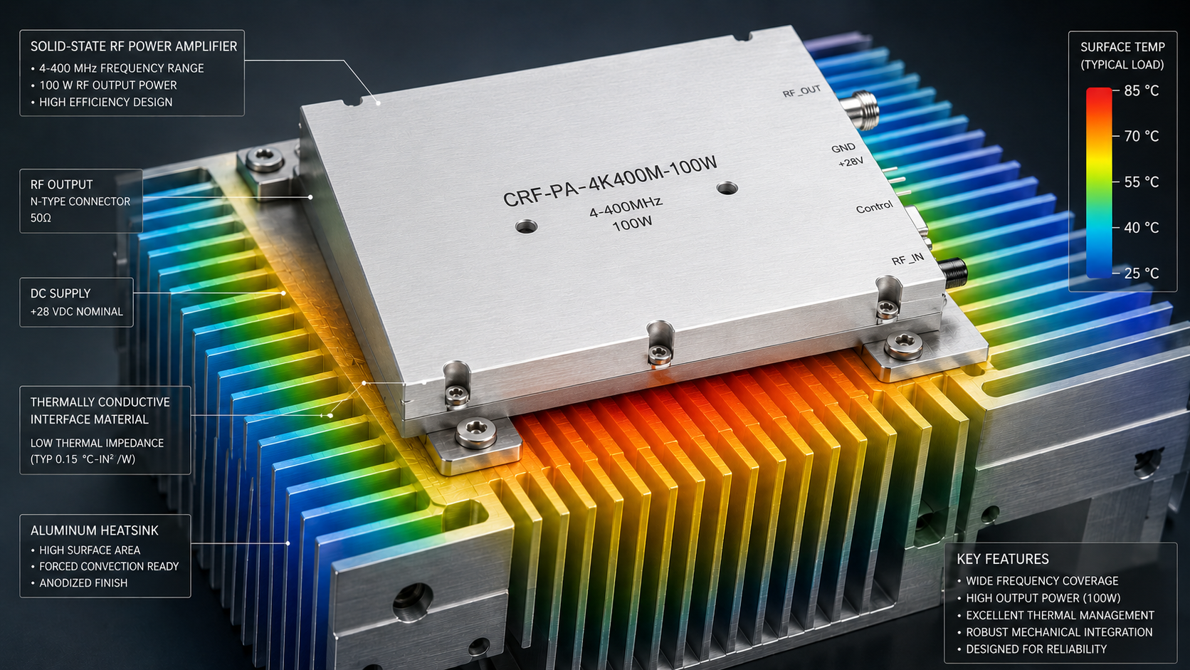
Many radio frequency system integration projects suffer severe delays during late-stage testing phases. Research engineers relying solely on a single-page datasheet face significant risks. Once integrated into an RF chain, systems often experience linearity degradation, interface impedance mismatch, and thermal runaway from inadequate cooling designs. Here is the deal: Marketing rhetoric cannot compensate for hardware design flaws. Establishing acceptance standards based on rigorous laboratory physical testing evidence remains critical for mitigating project risk. For test instrumentation, communication systems, or electronic warfare equipment, RF power amplifier acceptance logic must return back towards engineering truth. This article details scientific acceptance criteria and testing conditions covering three core aspects: S-parameters, output power, and gain flatness.
1. What Are Physical Mechanisms Regarding S-Parameters and Interface Impedance Matching?
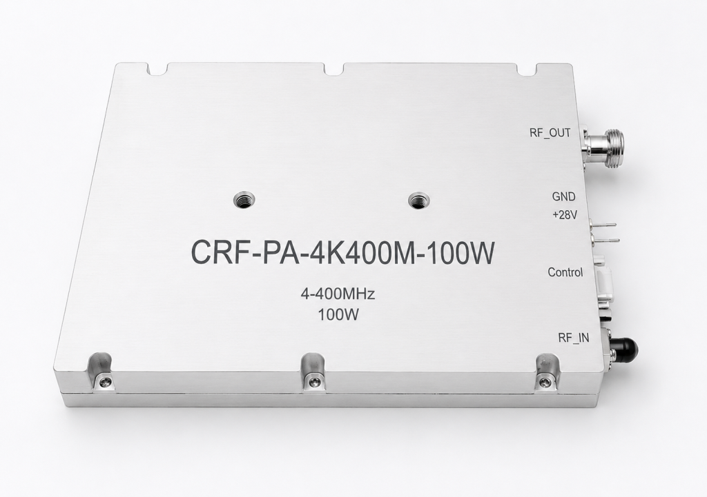
Any minor impedance discontinuity within a radio frequency transmission line causes energy reflection. When connecting an amplifier, a common pain point involves an excessively high Voltage Standing Wave Ratio caused by poor interface matching. S11 directly reflects matching degrees concerning an input port. Unabsorbed power reflects backwards when impedance mismatches exist between an interface and system feedline. During high-power applications, reflected energy directly impacts final-stage power transistor drains, reducing actual radiated power while risking core component destruction. You might be wondering: How do engineers verify this phenomenon? Simply checking nominal impedance values carries zero weight. True acceptance requires reviewing swept S-parameter test charts. Take CorelixRF ultra-wideband solid-state power amplifier CRF-PA-4K400M-100W as an example. This module provides industry-standard RF IN: SMA-F and RF OUT: N-F connectors. During Factory Acceptance Testing, engineers provide rigorous S11 swept data across frequencies spanning 4 kHz through 400 MHz. Furthermore, handling extreme mismatch conditions requires underlying hardware featuring VSWR overload protection alongside alarm functions. Such protection ensures physical cut-off regarding RF output during sudden load changes, protecting expensive system components.
| Parameter | Specification | Engineering Significance | Test Condition |
| Frequency Range | 4 kHz – 400 MHz | Determines operational bandwidth | Full band sweep |
| Input Impedance | 50 Ω typ. | System matching baseline | Calibrated VNA |
| VSWR | 2:1 max. | Reflection tolerance limit | Loaded output |
| RF Connectors | SMA-F In / N-F Out | Mechanical interface standard | Torque wrenched |
2. How Do We Balance Output Power Alongside System Linearity?
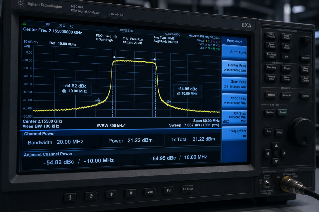
A nominal output specification frequently triggers disputes. Communications engineers often find that while an amplifier reaches maximum power, Error Vector Magnitude completely collapses. Nonlinear distortion stems from physical limits within transistors. Pushed into saturation regions, signals suffer severe compression, generating numerous intermodulation products despite achieving maximum output power. For systems requiring complex waveforms, truly valuable engineering metrics include 1dB compression points or linear output capacity under back-off conditions. This is where it gets interesting: Reviewing power acceptance reports requires demanding input-output power transfer curves from suppliers. CRF-PA-4K400M-100W utilizes an LDMOS SSPA platform design, delivering 100 W of solid-state RF output power within frequencies spanning 4 kHz through 400 MHz. Acceptance procedures must clearly define test conditions, specifying continuous wave or pulse signals alongside duty cycle parameters. If integrators demand extreme linearity, they confirm spectral regrowth data under specific modulation signals inside acceptance records. This module guarantees minimum small-signal gains reaching 50 dB, ensuring sufficient amplification margins supporting complex waveform fidelity.
| Performance Metric | Datasheet Value | Application Context | Verification Method |
| Saturated Power | >=100 W | Absolute maximum capability | CW signal drive |
| Small-Signal Gain | 50 dB min. | Amplification factor | Network Analyzer |
| Harmonics | -15 dBc typ. | Signal purity indicator | Spectrum Analyzer |
| Spurious | -50 dBc max. | Interference mitigation | Wideband sweep |
3. What Explains Direct Correlations Between Gain Flatness and Thermal Design?
Many amplifiers perform flawlessly initially, but gain drifts severely as operation time increases. This physical phenomenon usually results from thermal management failures. Semiconductor transistor gain reacts with extreme sensitivity towards junction temperature variations. As temperatures rise, carrier mobility decreases, directly causing small-signal gain drift. More severely, linear amplifiers typically operate with efficiencies between 20% and 40%. Generating high-power signals simultaneously produces massive heat dissipation. What is the real story? Gain flatness testing must occur under thermal equilibrium conditions, rather than capturing cold-state transients. CRF-PA-4K400M-100W promises small-signal gain flatness spanning -4 through +4 dB. From an engineering perspective, typical power consumption reaches 450 W, supplied by DC1: 48 V and DC2: 12 V inputs. Consequently, generating 100W converts over 300W of energy into heat. Therefore, mechanical form factors measuring 329.5 x 104.8 x 61 mm and weighing 3.5 kg explicitly mandate external heatsinks. CorelixRF integrates real-time temperature monitoring, alongside over-temperature protection circuits, preventing thermal runaway. Authentic FAT reports include gain curves under high-temperature operation proving thermal design reliability.
| Thermal & Mechanical | Value | Design Constraint | Impact |
| Power Consumption | 450 W typ. | High energy dissipation | Needs robust cooling |
| Power Supply | DC1: 48 V; DC2: 12 V | Dual rail requirement | PCB trace routing |
| Dimensions | 329.5 x 104.8 x 61 mm | Chassis integration | Spatial planning |
| Operating Temp | 0 to +40 °C | Environmental limits | Reliability boundary |
4. How Can Engineers Eliminate Common Disputes Through Strict Test Conditions?
Hearing complaints about factory testing failing inside customer systems remains a primary source of friction. Eliminating blame-shifting requires locking down strict testing environment baselines early during projects. First, establish system impedance baselines. All tests must occur within strictly calibrated 50 Ω systems, accounting for connecting cable losses. Second, define power and cooling baselines. Testing proceeds under rated 48V and 12V power supplies, simulating true airflow thermal resistance inside customer chassis environments. Ready for the good part? Standard catalog products rarely fit complex transmission chains perfectly. Addressing customer pain points regarding rapid modification, CorelixRF treats CRF-PA-4K400M-100W as standard hardware platforms. We quickly customize optional forward power monitoring interfaces, specific control protocol interfaces, and non-standard mechanical structural components based upon project demands. This approach significantly lowers secondary development risks for customers. Implementing robust diagnostics including real-time current monitoring ensures hardware safety across unpredictable testing scenarios.
| Protection Feature | Mechanism | Fault Trigger | Recovery Action |
| Over-temperature | Thermal sensor | Exceeding limit | Auto-shutdown |
| Over-drive | Input power limit | > 0 dBm input | Attenuation lock |
| Over-voltage | Voltage comparator | Supply spike | Power rail disconnect |
| VSWR Alarm | Directional coupler | High reflection | Output stage disable |
5. What Constitutes Logical Conclusions Alongside Next Steps For RF Project Integration?
Procuring an RF amplifier involves introducing a complex radio frequency energy conversion subsystem. Discarding impractical marketing promises while utilizing S-parameters, true linear power, and thermally loaded gain curves as sole acceptance credentials forms engineering baselines guaranteeing on-time project delivery. If your system integration project currently undergoes technical selection, demanding solid physical testing evidence reduces design risks. The bottom line presents itself clearly: Please submit target frequency ranges, output power, waveform types, CW operation, duty cycles, control interfaces, mechanical constraints, and environmental requirements. Schedule a CorelixRF 48-hour engineering review today. We directly provide technical drawings alongside testing data baselines matching actual working conditions. Manufacturing processes strictly follow ISO 9001 quality management systems, offering CE documentation support where applicable.
| Action Item | Required Input | Expected Deliverable | Timeline |
| Submit Specs | Frequency, Power, Waveform | Feasibility Report | Initial Phase |
| Define Interfaces | Control Protocol, Mechanical | Customization Proposal | Review Phase |
| FAT Verification | Thermal & RF baselines | Validated Test Data | Delivery Phase |
| Regulatory Check | Destination Market Rules | CE / RoHS Docs | Compliance Phase |
FAQ Section
Q1: What are S-parameters regarding RF amplifier acceptance?
S-parameters represent scattering matrices quantifying how RF energy travels through multi-port networks. Within amplifier acceptance, S11 measures input return loss indicating impedance matching quality. Proper evaluation prevents high voltage standing wave ratios that could damage final-stage transistors.
Q2: How does impedance mismatch affect RF power amplifiers?
Impedance mismatches cause energy reflections bouncing back towards the source. This reflected power generates standing waves along transmission lines, significantly increasing thermal stress across power components. It reduces effective radiated power while triggering built-in VSWR protection protocols shutting down module operations.
Q3: What causes nonlinear distortion within radio frequency systems?
Nonlinear distortion occurs when semiconductor devices operate near saturation regions causing amplitude compression. This physical limitation generates intermodulation products altering output spectrums. Such distortion severely degrades error vector magnitudes ruining complex modulation schemes like OFDM.
Q4: How does thermal management influence gain flatness?
Semiconductor junction temperatures directly dictate carrier mobility. Inadequate heatsinking causes rapid temperature spikes drastically reducing small-signal amplification capabilities over time. Maintaining gain flatness requires external heatsinks dissipating excess thermal energy maintaining continuous thermal equilibrium.
Q5: What baseline conditions should engineers establish during FAT?
Engineers must standardize calibrated 50-ohm test environments minimizing cable losses. Power supplies must maintain exact rated voltages under maximum load conditions simulating realistic chassis airflow. Defining continuous wave versus pulse operation alongside specific duty cycles prevents post-delivery performance discrepancies.
SEO Focus Keyphrase: RF Power Amplifier Acceptance
SEO Title: S-Parameters, Linearity & Thermals: RF Amplifier Acceptance Guide | CorelixRF
Meta Description: Discover scientific RF power amplifier acceptance testing. Review S-parameters, linearity, and thermal physics using CRF-PA-4K400M-100W lab data. Schedule an engineering review mitigating project risks.
Define acceptance testing before the purchase order
Acceptance testing should be measurable and repeatable. Confirm frequency points, output power, gain flatness, harmonic limits, VSWR protection behavior, thermal soak, control interface and report format before placing the order.
Recommended next step: send the operating band, required output power, duty cycle, load condition, control interface, cooling limit, protection behavior and required FAT documents. CorelixRF can map this RF power amplifier acceptance testing requirement to a standard platform, a controlled modification or a custom RF build.