
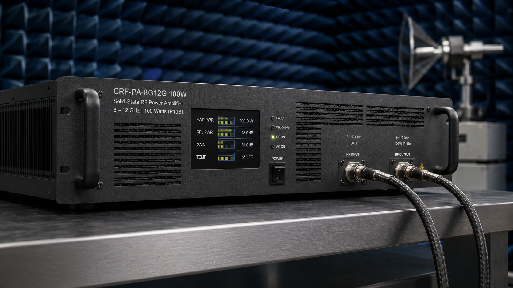
RF Engineering Guide
VSWR protection should be evaluated against agreed mismatch conditions—not accepted as a generic datasheet claim. This guide explains the relevant failure mechanisms, protection decisions and FAT evidence buyers should define before shipment.
Why an “Integrated VSWR Protection” Claim Is Not Enough
High-power RF amplifiers are often connected to antennas, cables, switches, couplers and test fixtures whose impedance changes with frequency, installation and operating environment. A nominal 50 Ω system can therefore present a substantially different load to the amplifier at particular frequencies or under fault conditions.
A datasheet statement such as “VSWR protection included” confirms that a protection concept exists, but it does not define the conditions under which the function operates. A buyer still needs to understand the detection threshold, protection action, recovery logic, operating limits and evidence that will be supplied during factory acceptance.
It is whether the protection behavior is suitable for the project’s frequency range, power level, duty cycle, cooling arrangement, expected load conditions and control architecture.
How Load Mismatch Stresses an RF Power Amplifier
Safe power transfer depends on maintaining an acceptable impedance match between the amplifier, transmission line and load across the operating frequency range. When the load departs from the nominal system impedance, part of the incident RF energy is reflected toward the amplifier.
Under severe mismatch, the reflected wave changes the voltage and current stress presented to the output device. The result depends on reflection phase, device architecture, operating power, duty cycle, thermal conditions and protection response. It is therefore inaccurate to treat all reflected power as being converted directly into heat inside the amplifier.
Electrical stress
The forward and reflected waves combine at the amplifier output. Different reflection phases can produce different voltage and current maxima at the output device and matching network. A protection strategy should therefore be assessed against defined load conditions rather than a single ambiguous “high VSWR” statement.
Thermal and stability considerations
Mismatch can alter device dissipation, efficiency and stability. The risk is affected by output power, exposure duration, waveform, duty cycle, heatsink temperature and airflow. A short controlled event and sustained operation into a poor load are not equivalent test conditions.
Protection Behavior Buyers Should Define
Different amplifier platforms may use different methods to reduce device stress. The appropriate behavior should be agreed for the selected model and application rather than assumed from a generic feature label.
Detection
The design may monitor reflected power, a derived VSWR value, device current, temperature or a combination of signals.
Power reduction
The amplifier may reduce drive or output power after the defined protection criterion is reached.
Mute or shutdown
Some projects require the RF path to mute or the amplifier to enter a protected state until conditions are safe.
Recovery and reporting
Recovery may be automatic, timed or manually reset. Alarm, telemetry and remote-control behavior should be specified with it.
Recommended VSWR Protection FAT Framework
The following framework is a requirements checklist, not a declaration that every amplifier has been tested under the same conditions. The final procedure should be agreed by the buyer and manufacturer for the selected platform.
| FAT item | Requirement source | Evidence to request |
|---|---|---|
| Mismatch threshold | Buyer-defined or manufacturer-declared | Forward/reflected-power record and alarm state |
| Load condition | Project-specific | Agreed load, duration, frequency and phase conditions |
| Protection response | Manufacturer-declared | Time-domain trace or controller event record |
| Protection behavior | Project-specific | Foldback, mute or shutdown state, if implemented |
| Recovery behavior | Project-specific | Automatic or manual recovery sequence |
| Thermal condition | Agreed acceptance plan | Supply, duty cycle, ambient, airflow and temperature record |
| Post-test verification | Agreed acceptance plan | Before/after gain, output and spectral comparison |
Numerical limits should only be published when they belong to a confirmed model specification or an approved project test plan. A threshold or response target suitable for one platform may not represent another frequency band, power class or operating mode.
How Baseline RF Measurements Support the Acceptance Record
Normal-load measurements establish the amplifier’s condition before and after any agreed protection test. Useful records may include small-signal gain, input matching, output power, harmonics, supply current and temperature at defined frequency points.
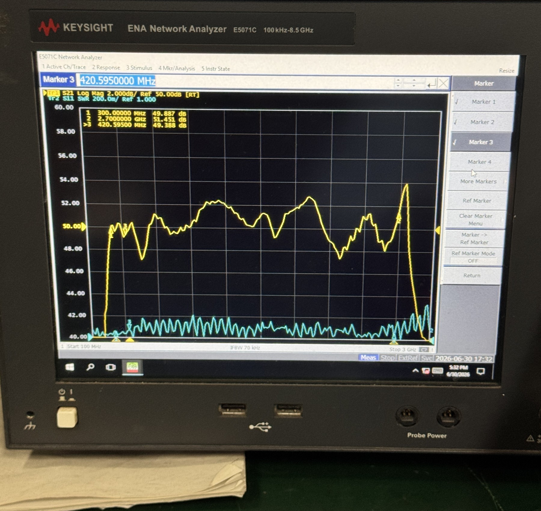
Evidence boundary: The representative small-signal measurement used with this article documents S21 gain and S11 input matching under a nominal 50 Ω laboratory setup. It is not a high-power output-mismatch survival test and does not establish a protection threshold or response time.
A measurement image should identify the model or platform, instrument, frequency span, trace type and relevant markers. A production data table should also state units, supply conditions, operating mode and measurement method. Unexplained fields or values should be clarified before the record is shared with a customer.
What to Include in a VSWR Protection RFQ
A concise set of operating requirements allows engineering teams to determine whether a standard protection implementation is appropriate or whether a controlled customization and test plan is required.
- Frequency rangeStart and stop frequency, including any priority sub-bands.
- Output requirementRated power, linear or saturated operation and acceptable power reduction.
- Operating modeCW or pulsed operation; include duty cycle and pulse information when applicable.
- Expected loadNormal antenna/load condition and any credible mismatch or disconnection scenario.
- Protection preferenceFoldback, mute, shutdown, alarm behavior and permitted retry logic.
- Recovery behaviorAutomatic recovery, timed retry or manual reset requirements.
- Thermal environmentAmbient range, airflow, heatsink or cold-plate interface and installation limits.
- Acceptance evidenceRequired plots, event records, test table, report format and witness-test needs.
VSWR Protection and FAT Questions
Does an input-VSWR measurement prove output mismatch protection?
No. An S11 input-VSWR trace documents input matching under the measurement setup. Output mismatch protection requires a separately defined high-power procedure and evidence.
Should every amplifier be tested with the same mismatch condition?
No. The load, duration, frequency points, power level and operating mode should be appropriate for the selected platform and the buyer’s real application.
Should recovery be automatic after the load returns to normal?
That is a system decision. Automatic recovery can reduce downtime, while a latched shutdown may be preferred where repeated retries could create risk. The desired behavior should be specified before FAT.
What baseline data should be recorded?
Typical records include gain, output power, harmonics, input matching, supply current and temperature at agreed frequency points. The final set depends on the amplifier and acceptance plan.
Can CorelixRF provide one universal VSWR protection limit?
Protection limits and behavior depend on the selected model, power class, frequency range and operating conditions. Engineering review is required before a project-specific value is confirmed.
Define the VSWR Protection Requirement Before FAT
Send the frequency range, output power, operating mode, duty cycle, expected load conditions, preferred recovery behavior and required test records. CorelixRF can review which protection functions and acceptance evidence should be included for the selected platform.