
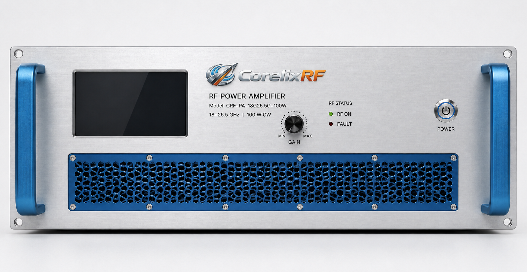
Many EMC (Electromagnetic Compatibility) laboratories make a costly mistake when building Radiated Immunity testing systems: they reverse-engineer the required RF amplifier rated power based solely on the target field strength and ideal antenna gain, then simply look for a matching number in a product catalog. However, once the equipment is actually running in the anechoic chamber, they discover that the specified V/m field strength cannot be achieved on the test plane. Worse, the amplifier might overheat and shut down, or components may be damaged during prolonged frequency sweep tests.
For product-level review, compare EMC RF amplifiers for immunity testing before finalizing frequency range, output power, duty cycle and documentation requirements.
The root cause of such project failures lies in ignoring insertion loss in the RF link, antenna impedance mismatch, and the amplifier’s continuous operating capability under extreme conditions during the selection phase. This article will delve into the core engineering metrics of EMC amplifier selection from the perspectives of physical mechanisms and laboratory test data, providing a practical acceptance and selection workflow.
The Engineering Truth Behind Achieving Field Strength: Cable Loss, VSWR, and 100% Frequency Matching
In EMC testing, the Rated Output Power at the RF power amplifier’s output flange never equals the effective power ultimately radiated onto the surface of the Equipment Under Test (EUT). There are physical loss mechanisms between the amplifier and the antenna that cannot be ignored.
- 1. Insertion Loss and Transmission Attenuation in High-Frequency Bands: In microwave and millimeter-wave bands (e.g., 18 GHz to 26.5 GHz), the insertion loss of RF cables or waveguides is highly significant. If power is calculated assuming only ideal conditions—without factoring in feeder line loss, directional coupler loss, and connector insertion loss—the actual power reaching the antenna feed point will shrink drastically. Therefore, the amplifier’s rated power must be based on rigorous Link Margin calculations, not simple theoretical reverse-engineering.
- 2. Impedance Mismatch and the Impact of VSWR: An anechoic chamber is a complex electromagnetic space. The Voltage Standing Wave Ratio (VSWR) of broadband log-periodic or horn antennas is not constant across different frequency points. Additionally, high-reflectivity EUTs will bounce a massive amount of RF energy back to the transmitting end. This impedance mismatch not only causes a sudden drop in forward transmit power but, in severe cases, the reflected power will directly impact the final-stage GaN (Gallium Nitride) transistors of the amplifier. If the amplifier lacks reliable VSWR protection and overload diagnostic mechanisms, the transistors are highly susceptible to complete failure due to thermal or voltage breakdown.
- 3. The “100% Coverage Principle” for Frequency Band Matching: To ensure absolute system compatibility and test data compliance, the technical matching logic dictates that the RF amplifier’s operating frequency band cannot merely “partially overlap” with the antenna’s frequency band; it must achieve 100% coverage of the required testing band. Any blind spots or power drops at the band edges will directly result in a failure to meet immunity testing standards at those specific frequencies.
Continuous Operation and Thermal Derating: The Lifeline of Stable Output
EMC immunity testing often requires continuous operation for hours or even days, following specific Dwell Times and step frequencies. Under such Continuous Wave (CW), Amplitude Modulation (AM), or pulse modulation operating states, thermal management becomes the key factor deciding the amplifier’s survival.
Solid State Power Amplifiers (SSPAs) generate massive heat dissipation while amplifying power. If the cooling system is poorly designed, an increase in transistor Junction Temperature will directly lead to Gain Drift and degraded linearity. This means that even if an amplifier hits 100W output the moment it is turned on, its actual output power could experience a cliff-like drop after an hour of continuous full-load operation, halting the test.
High-spec, industrial-grade amplifiers must resolve thermal bottlenecks right at the design phase. Examples include adopting thermodynamically simulated air-cooling or water-cooling rack structures to ensure long-term, stable operation at a 100% duty cycle, and providing detailed burn-in and temperature drift curves during factory testing.
Standardized Workflow for Proper Selection and Acceptance
To completely eliminate “blind box” risks during procurement and system integration, EMC labs should not rely solely on a one-page spec sheet from a product manual. Instead, they should establish a rigorous selection and acceptance workflow (FAT/SAT) based on “engineering evidence”:
- Define System-Level Boundary Conditions: Before requesting a quote (RFQ), provide the complete target field strength (V/m), test distance, Antenna Factor (AF), and estimated cable loss values.
- Request P1dB and Linearity Data: For stringent Amplitude Modulation (AM) testing, the amplifier must operate within a certain Back-off range to ensure envelope integrity. When purchasing, always request P1dB compression point data and S-parameter sweep plots, rather than just looking at the saturated output power (Psat).
- Review Protection Mechanisms and Control Interfaces: Verify whether the equipment features real-time temperature/current monitoring, Forward/Reverse Power Monitoring, and hardware-level alarm protection functions.
- Execute FAT (Factory Acceptance Testing): Insist on obtaining the actual pre-shipment test report for the specific serial number device. Verify its survivability under extreme VSWR conditions and its thermal stability during prolonged full-power operation.
CorelixRF’s Differentiated Delivery: A Case Study on the CRF-PA-18000M26500M-100W
As a manufacturing facility dedicated to the R&D of high-reliability RF hardware, CorelixRF refuses to mask technical details with vague marketing jargon. We consistently insist on delivering system-level solutions backed by empirical laboratory evidence.
Tailored for the demanding high-frequency EMC testing and Electronic Warfare (EW) system-level immunity testing from 18 GHz to 26.5 GHz, the CRF-PA-18000M26500M-100W delivers rigorously validated engineering performance:
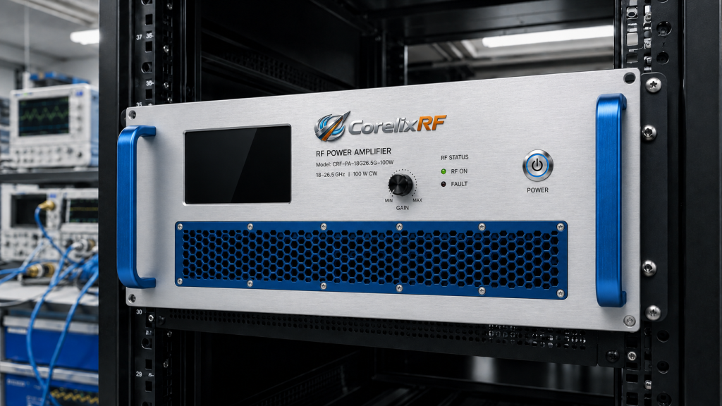
- Seamless Frequency and Power Coverage: Built on an advanced GaN SSPA platform, it achieves 100% full-band coverage from 18 to 26.5 GHz. It provides 100W of rated output power and a minimum small-signal gain of 50 dB, easily compensating for steep high-frequency cable losses.
- Industrial-Grade Reliability Architecture: Featuring a standard 19-inch 4U Rack-Mount design, the unit has a typical power consumption of 800W. Combined with a highly efficient forced air cooling thermal management system, it completely resolves gain drift issues during continuous operation.
- Comprehensive Self-Diagnostics and Protection Interfaces: Comes standard with a 2.92mm-F RF input and WR42 waveguide output. The system features built-in temperature and current diagnostic mechanisms, offers RS485 / LAN remote control protocols, and supports forward/reverse power monitoring alongside seamless integration. This ensures the core RF modules are effectively protected against antenna mismatches.
Do not let an unverified RF amplifier become the weakest link in your EMC testing system. Reliable field strength comes from rigorous link calculations and authentic factory test data.
[Call to Action]
Ready to upgrade your radiated immunity testing system? Schedule a 48-hour engineering review with CorelixRF. Our technical team will conduct precise link calculations based on your antenna parameters and target field strength. Alternatively, download our standard FAT (Factory Acceptance Test) Checklist Template directly to take control of your next procurement cycle.
Use EMC amplifier requirements as a procurement checklist
EMC replacement and immunity-test amplifier projects should confirm usable frequency range, field-strength target, load mismatch behavior, duty cycle, control method and calibration documents. A clear RFQ package helps us recommend whether an existing platform or a modified build is the better route.
Recommended next step: send the target band, output power, duty cycle, load condition, control interface, cooling limit and required FAT documents. CorelixRF can map this EMC RF power amplifier selection requirement to a standard platform or a controlled customization path.