
In electromagnetic compatibility (EMC) system integration and the construction of high-power radio frequency (RF) test platforms, system integrators consistently encounter three core engineering risks: failure to meet target field strength requirements during final site acceptance, thermal attenuation or catastrophic downtime of power amplifier modules under continuous-wave (CW) operating conditions, and ambiguous post-sales liability demarcation when load reflection faults occur.
Relying solely on a marketing-oriented datasheet is insufficient to mitigate these systemic risks. Procurement decision-makers are frequently misled by peak parameters specified under idealized laboratory conditions, completely overlooking the boundary condition constraints of RF hardware during actual system integration. To guarantee successful project delivery and minimize integration-level liabilities, system integrators must look beyond unit pricing and demand explicit system delivery transparency from their suppliers. The following analysis outlines the five core delivery documents that clients must prioritize and mandate from vendors at critical project milestones.
1. RF Performance & Linearity Test Data
Purpose: Mitigating the Root Cause of Non-Compliant Field Strength
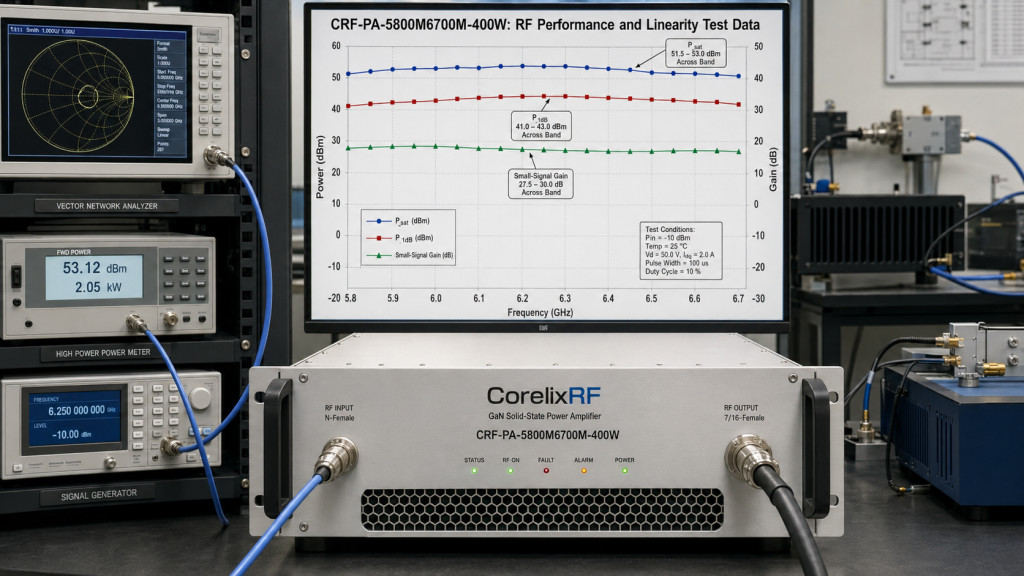
In EMC immunity testing, the generated field strength within the target anechoic or semi-anechoic volume scales directly with the actual RF output power and frequency flatness of the amplifier system. If the power amplifier exhibits severe gain drift or localized power dropouts at specific frequency points, the system integrator faces the critical risk of failing site validation. The actual test report must provide empirical curves mapping small-signal gain (59dB minimum), saturated output power (Psat), and the dB compression point (P1dB) across the entire operating band.
Engineering Mechanisms & Physical Principles
When evaluating RF power metrics, engineers must rigorously differentiate between Continuous Wave (CW) and Pulsed RF applications. CW operation demands sustained, uninterrupted thermal dissipation and power delivery from the amplifier. Conversely, pulsed applications require meticulous evaluation of pulse fidelity, rise/fall times, and pulse droop. The Gallium Nitride (GaN) Solid-State Power Amplifier (SSPA) architectures designed by CorelixRF strictly align with these underlying device physics. Every empirical test report explicitly documents the exact modulation and stimulus types utilized during testing, strictly prohibiting the deceptive practice of inflating CW ratings using low-duty-cycle pulsed metrics.
- Delivery Milestone: Provided concurrently with prototype delivery or during the Factory Acceptance Testing (FAT) phase.
2. VSWR & Over-drive Protection Log
Purpose: Verifying System Survivability Under Extreme Operational Boundaries
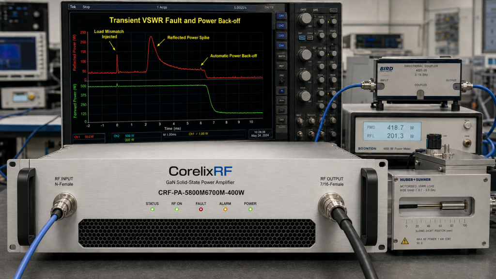
The operational loads of system integrators typically consist of wideband antennas or directional couplers. During automated frequency sweeps, the input impedance of the antenna shifts drastically as a function of frequency, inevitably inducing severe impedance mismatch conditions. The protection validation log serves as empirical proof of the amplifier’s automated defensive actions when subjected to high reverse reflected power.
Engineering Mechanisms & Physical Principles
Voltage Standing Wave Ratio (VSWR) escalates abruptly, the reflected RF energy propagating back into the amplifier combines with the forward wave, causing standing wave voltage superposition at the output stages. This mechanism easily leads to the electrical breakdown of GaN or LDMOS dies. A compliant protection log must document the millisecond-level response times of the amplifier’s internal forward and reverse power monitoring circuits as they trigger automated power back-off or hard shutdown sequences under severe antenna mismatch, preventing cascaded device failure.
- Delivery Milestone: Historical design logs of identical topologies provided during the engineering review phase; project-specific empirical validation logs delivered during FAT.
3. Thermal Management & Burn-in Report
Purpose: Ensuring Long-Term Operational Reliability and Eliminating Thermal Shutdown Liabilities
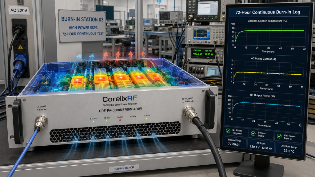
A vast majority of high-power RF amplifier project failures stem directly from thermal management breakdown. The burn-in report validates the thermal equilibrium state of the equipment under nominal full-load conditions.
Engineering Mechanisms & Physical Principles
Consider the CorelixRF standardized high-frequency platform model CRF-PA-5800M6700M-400W, which delivers a rated output power of 400W across the 5.8GHz to 6.7GHz spectral band. Under high-voltage (AC220V) full-load drive conditions, the channel junction temperature of the GaN active devices escalates rapidly. If the forced air-cooling system geometry is sub-optimal, or if the thermal interface materials (TIM) undergo “pump-out” effects due to cyclic thermal expansion, localized thermal runaway will occur. The burn-in log must contain continuous temperature and current monitoring data spanning a minimum of 48 to 72 hours of uninterrupted full-power operation, explicitly verifying the exact activation thresholds for current and temperature alarms.
- Delivery Milestone: Delivered one week prior to physical equipment dispatch, serving as a mandatory gate for shipping clearance.
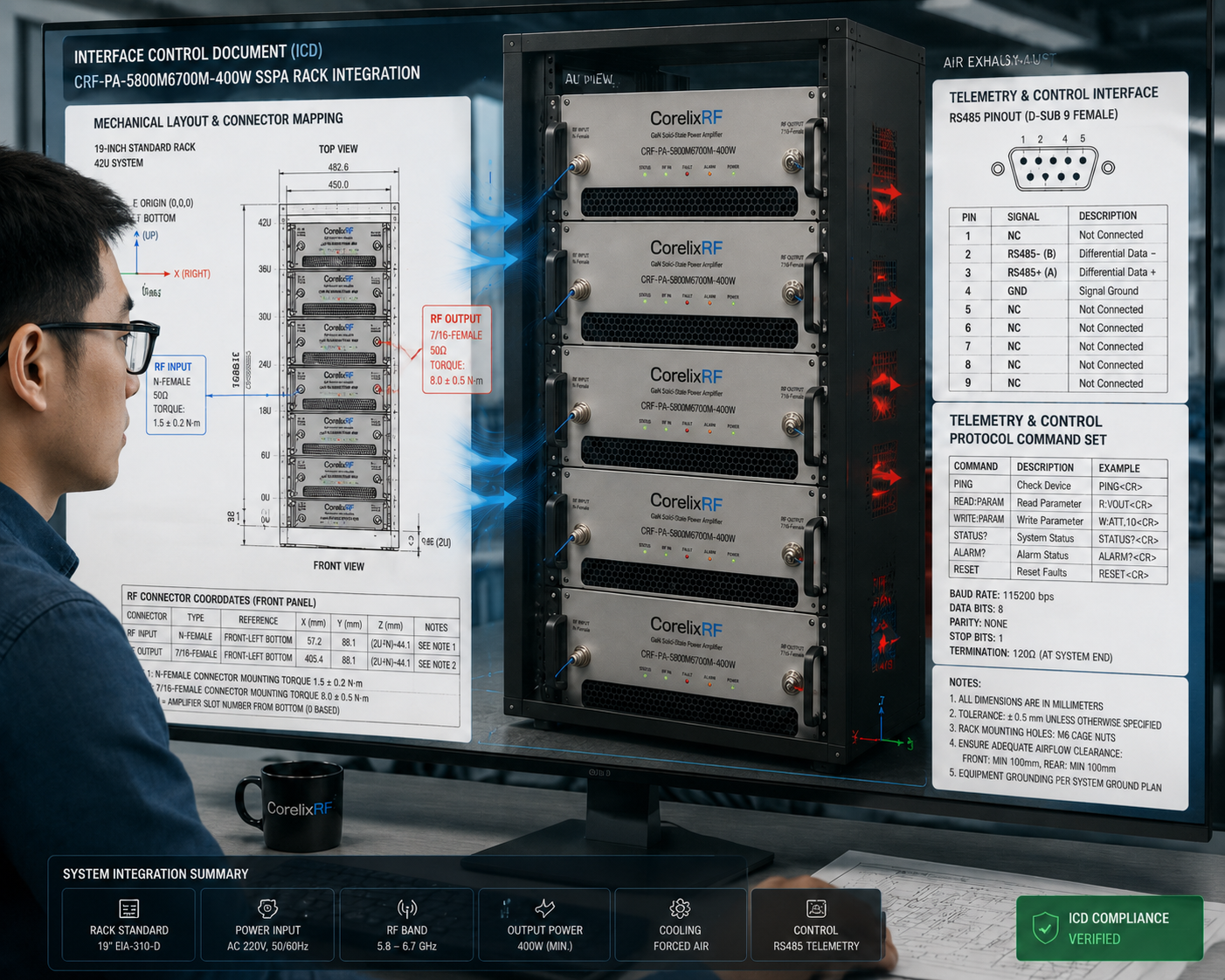
4. Interface Control Document (ICD)
Purpose: Guaranteeing Seamless Mechanical Integration and Remote Telemetry/Control Interoperability
Rack-level system integration extends far beyond placing an instrument into an enclosure; it requires the precise management of airflow dynamics, RF cable strain relief, and remote control protocol mapping.
Engineering Mechanisms & Physical Principles
The ICD must explicitly define the exact physical coordinates and mechanical torque specifications for all RF interfaces. For instance, the input port might utilize an N-Female connector, whereas the high-power RF output port must mandate a 7/16-Female connector to safely sustain hundreds of watts of continuous-wave power without dielectric degradation. Furthermore, the document must detail the exact locations of the forced air intake and exhaust vents to prevent the formation of localized thermal pockets within the integrated rack system. On the telemetry side, the RS485 control interface pinouts and the complete remote control protocol command set must be locked down within the ICD to prevent costly software debugging delays during field integration.
- Delivery Milestone: Delivered during the initial requirements definition and project kick-off phase (Milestone 1).
5. Factory Acceptance Test Specification (FAT Protocol & RMA SLA)
Purpose: Demarcating Post-Sales Liability Boundaries and Formalizing Quality Service Level Agreements
The most effective method to eliminate post-delivery commercial and technical disputes is to establish unambiguous, quantifiable acceptance criteria prior to shipment. The FAT protocol strictly dictates the physical boundaries of system performance evaluation.
Engineering Mechanisms & Physical Principles
The FAT protocol translates all critical technical metrics—including operating frequency bands, absolute power output, harmonic suppression, VSWR mismatch survival, and communication telemetry interfaces—into a binary, itemized testing procedure. It eliminates all subjective interpretations, relying exclusively on traceable laboratory instrumentation data. Only when engineers from both the vendor and the integrator verify that every physical parameter satisfies or exceeds the contract baseline is the hardware authorized for secure packaging and deployment to the integration site.
- Delivery Milestone: Finalized and executed as a mandatory technical appendix prior to contract signature.
True industrial-grade RF manufacturing rejects speculative or idealized parameters. It operates solely on Engineering Truth—performance verified strictly by laboratory-grade instrumentation. From standardized platform modules to highly complex, deep-customized multi-kilowatt rack systems, delivery transparency represents the only reliable methodology for mitigating risk in high-power system integration.
Next Steps:
Establish a rigorous quality baseline for your upcoming RF integration project.
[Download the FAT Template] immediately, or consult with a CorelixRF application engineer to [Schedule a 48-Hour Engineering Review]. We will provide a data-driven RF hardware selection strategy tailored precisely to your actual field deployment environment.
Prepare the document package before ordering rack-mounted amplifiers
For rack-mounted RF power amplifiers, the purchasing risk is usually hidden in interfaces, acceptance curves and delivery documents. Share the required datasheet fields, FAT curves, connector layout, control protocol and installation limits before quotation.
Recommended next step: send the target band, output power, duty cycle, load condition, control interface, cooling limit and required FAT documents. CorelixRF can map this rack-mounted RF power amplifier documents requirement to a standard platform or a controlled customization path.