
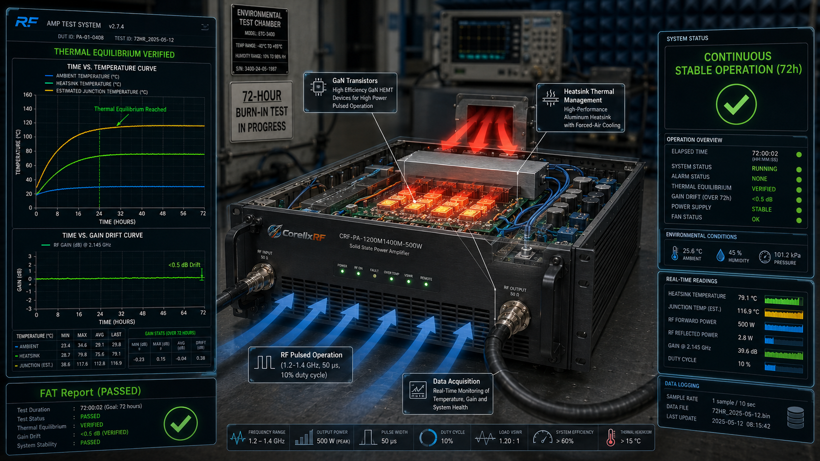
For EMC laboratories, radar simulation systems, and Electronic Warfare (EW) system-level testing, the most fatal project risk is often not that the RF Power Amplifier (RF PA) fails to meet its nominal power, but rather unpredictable field strength degradation or system shutdown after hours of continuous operation.
When making selection decisions, many engineers and procurement decision-makers tend to focus solely on the room-temperature specifications listed on the datasheet, ignoring the thermodynamic performance under continuous laboratory working conditions. When an amplifier operates at full load for an extended period, flawed thermal design will lead to an abnormal rise in Junction Temperature. This directly causes gain drift, linearity degradation, and may even trigger false Voltage Standing Wave Ratio (VSWR) protection.
To ensure the field strength meets standard requirements, guarantee continuous operational capability, and reduce after-sales uncertainty, procurement and quality assurance departments cannot base their acceptance solely on a single page of static parameters. Starting from underlying engineering mechanisms, this article details how to rigorously verify the thermal stability of RF PAs under long-term continuous operation using burn-in and temperature rise curves.
The Engineering Mechanism Behind Field Strength Degradation: Heat Accumulation and Gain Drift
Before discussing testing standards, it is essential to understand the physical mechanisms causing these pain points. Taking a GaN (Gallium Nitride) based pulsed power amplifier as an example, the conversion loss of RF energy during operation translates into a massive amount of heat.
In pulsed operation mode (e.g., pulse width of 50 μs, duty cycle of 10%), although the average power dissipation is lower than in Continuous Wave (CW) mode, the power transistors undergo high-frequency Thermal Cycling. If the thermal resistance of the heatsink is too high, or if the thermal interface material suffers from the “pump-out effect” due to long-term thermal expansion and contraction, heat cannot be effectively dissipated into the external environment.
When internal heat accumulation drives the die temperature close to its limit, the mobility of semiconductor charge carriers drops significantly. The direct observation on the testing end is that while the input power remains constant, the output power slowly declines (i.e., gain drift). Simultaneously, high temperatures alter the impedance characteristics of internal RF microwave components, exacerbating impedance mismatch and increasing reflected power. Ultimately, this can force the amplifier into a protective shutdown due to overheating or excessive reflection. This is the root cause of sudden field strength failures during continuous testing.
Therefore, to verify whether an RF power amplifier is truly qualified, it must be subjected to extreme testing conditions to observe its dynamic performance through comprehensive burn-in and temperature rise curves.
Core Verification Step 1: Establish Stringent Laboratory Testing Conditions
Thermal stability verification cannot be divorced from specific application waveforms. The setup of testing conditions must strictly align with the product’s physical limits and actual application scenarios.
Take the CorelixRF CRF-PA-1200M1400M-500W Pulsed Solid State Power Amplifier (SSPA) as an example. This module is primarily designed for the 1.2 GHz to 1.4 GHz frequency band, with a nominal pulsed output power of 500W. When conducting pre-factory thermal stability verification, we require the establishment of the following baseline testing conditions:
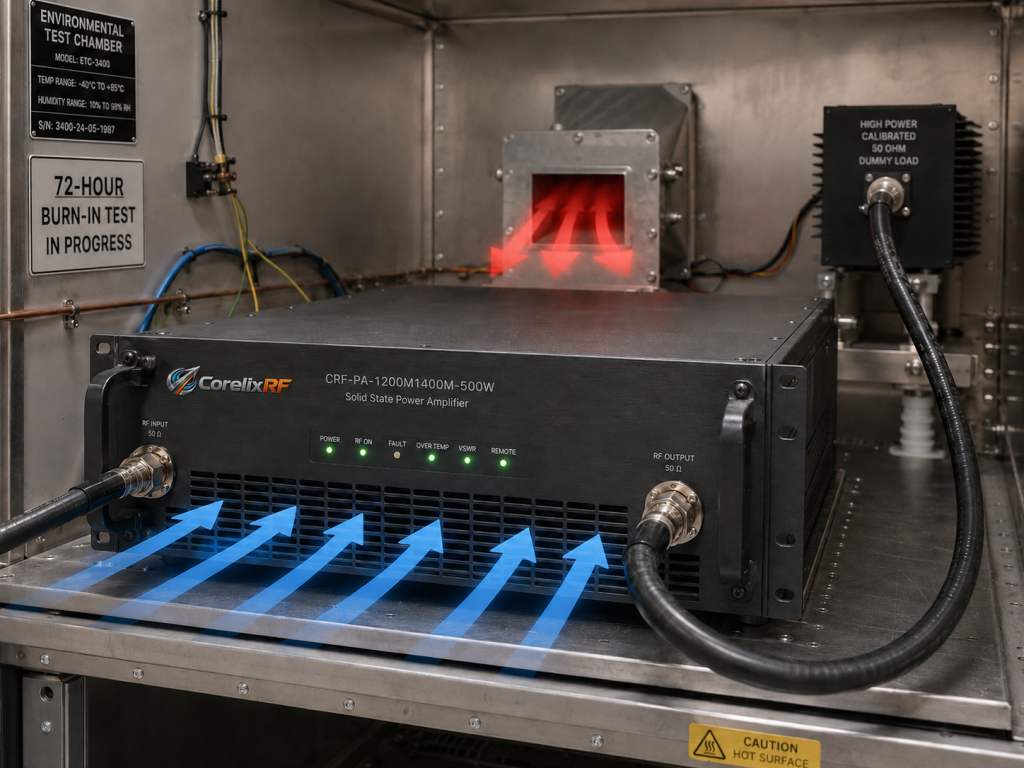
- Input Stimulus Definition: Strictly set according to the datasheet. The input signal must be an RF pulsed signal between 1.2-1.4 GHz, with a typical pulse width of 50 μs and a maintained duty cycle of 10%. Using Continuous Wave (CW) signals for thermal testing of a pulsed power amplifier is strictly prohibited to prevent excessively high average power from destroying the equipment or generating thermal conduction data inconsistent with actual scenarios.
- Environmental and Load Constraints: Place the amplifier in an environmentally controlled test chamber (typically a 25°C base room temperature, which can be deviated to extreme operating temperatures). The RF output port must be connected to a calibrated 50-ohm high-power attenuator or load, ensuring a base VSWR of less than 1.2:1.
- Forced-Air Cooling Environment Simulation: This model utilizes a standard 3U Rack-Mount chassis equipped with forced-air cooling. Testing must simulate the actual air duct resistance within a cabinet to verify the cooling efficiency of its fan array under real-world installation conditions.
- Long-Term Duration: Continuously apply the stimulus signal to operate the device for no less than 72 hours.
Core Verification Step 2: Multi-Dimensional Data Recording Methods
During the 72 hours of continuous full-load operation, the test is not merely about “powering on” the machine, but rather a high-density data acquisition process. Standardized laboratory acceptance should require suppliers to provide the following two core curves:
- Time vs. Temperature Curve: Utilize internally integrated temperature diagnostics interfaces and external surface-mount thermocouples to synchronously record the ambient temperature, the heatsink baseplate temperature, and the temperature of critical internal RF link components. A qualified temperature rise curve should reach a smooth asymptote (i.e., thermal equilibrium) within 1-2 hours of full-power operation and remain relatively constant over the subsequent dozens of hours. If the curve exhibits a stepped pattern or continuous, non-converging rise, it indicates that the cooling system is on the verge of collapse.
- Time vs. Gain Drift Curve: Throughout the burn-in test period, continuously monitor the forward output power and reflected power via a directional coupler. For the CRF-PA-1200M1400M-500W, its minimum gain under nominal conditions is 57 dB. The maximum Gain Droop within this 72-hour timeframe must be recorded. Additionally, it is necessary to monitor whether the single-pulse Pulse Droop deteriorates under high-temperature steady states.
Furthermore, the product features built-in current diagnostics and alarm protection mechanisms. During the recording process, real-time power consumption data must be captured via RS485 or LAN control interfaces to ensure that the power supply module (220 V AC powered) does not experience abnormal current fluctuations due to thermal derating.
Core Verification Step 3: Clear Assessment Criteria and Engineering Acceptance
After obtaining the burn-in and temperature rise curves, procurement and quality departments need clear assessment criteria:
- Establishment of Thermal Equilibrium and Threshold Assessment: Under continuous pulsed full-load operation, the equipment must reach thermal equilibrium within a specified timeframe. The baseplate temperature and the estimated internal die temperature must remain below the safe thermal derating limits of the GaN devices. No over-temperature alarm shutdowns are permitted during the test.
- Gain and Power Drift Limits: During the 72 hours of continuous operation, RF output power fluctuations after the establishment of thermal steady-state must be controlled within an extremely small margin allowed by engineering standards (typically required to be no more than 0.5 dB to 1 dB, depending on protocol specifications). The field strength must consistently meet laboratory system testing standards.
- Interference Immunity of Protection Mechanisms: The tolerance of the RF link changes under high temperatures. The assessment criteria should mandate: under thermal equilibrium, the equipment’s VSWR protection circuits must not trigger falsely.
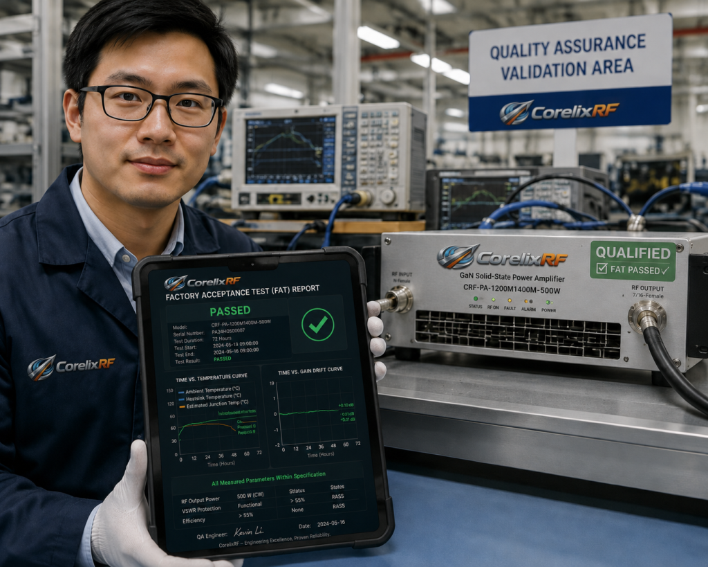
Eliminating Procurement Acceptance Risks: Requesting Empirical Evidence
Regardless of how flawlessly the technical parameters are written on a datasheet, without the backing of factory empirical data, system integrators and laboratories will bear immense risk during final Site Acceptance Testing (SAT).
At CorelixRF, we refuse to use ambiguous terms like “perfect” or “absolute.” Through a standard Factory Acceptance Test (FAT) process, we provide detailed empirical evidence for every CRF-PA-1200M1400M-500W system delivered. Whether it is a 50 μs / 10% duty cycle pulse waveform capture or the temperature rise and gain records during long-term burn-in, these are submitted to the customer as mandatory deliverables. Only rigorous verification based on physical data can truly eliminate the anxieties of procurement and quality acceptance.
Ready to procure a high-reliability pulsed power amplifier for your next EMC or radar testing project?
Do not make a decision based solely on a product catalog. Contact our engineering team to request complete test data and acceptance guidelines, or to conduct an in-depth technical feasibility analysis based on your specific parameter requirements.
👉 [Download CorelixRF Industrial-Grade FAT / SAT Acceptance Standard Template]
👉 [Submit RFQ: Schedule an Advanced Engineering Review within 48 Hours]
Link thermal stability to EMC amplifier acceptance evidence
EMC amplifier buyers should ask for the frequency points, output power, duty cycle, thermal soak condition, gain drift limit and FAT report format. That turns a reliability question into a factory-verifiable acceptance plan.
Recommended next step: send the operating band, required output power, duty cycle, load condition, control interface, cooling limit, protection behavior and required FAT documents. CorelixRF can map this RF amplifier thermal stability for EMC tests requirement to a standard platform, a controlled modification or a custom RF build.