
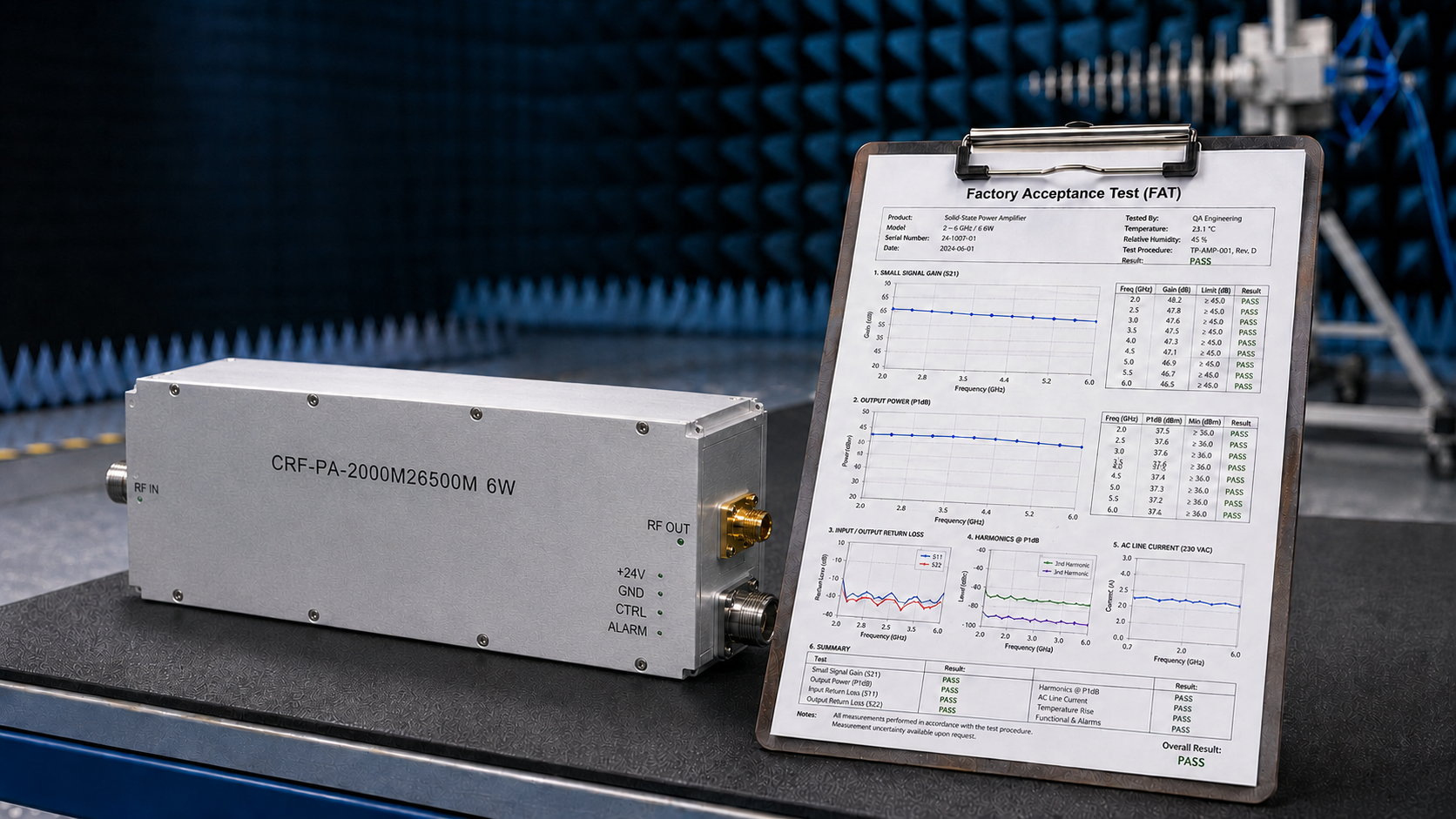
In the complex integration and continuous upgrading of Electromagnetic Compatibility (EMC) test systems, project managers and lead engineers frequently confront a severe engineering challenge: the procured Radio Frequency Power Amplifier (RF PA) completely meets all specifications on the paper datasheet, yet fails to pass system integration during the final Factory Acceptance Test (FAT) or Site Acceptance Test (SAT).
The core reason behind this critical pain point is rarely a deficit in the absolute physical power of the amplifier. Instead, it stems from a critical failure by procurement departments and engineering teams to clearly define the specific test conditions and physical boundaries that govern those parameters during the initial quoting phase.
This ambiguity in early-stage specifications creates an operational loophole for certain suppliers to provide “exaggerated” or “ideal-condition” data. The inevitable results are endless technical disputes during the acceptance phase, severe delays in project timelines, and a prolonged, highly inefficient Return Merchandise Authorization (RMA) process. For project managers tasked with controlling strict timelines and budgets, the only method to eliminate these uncertainties is to abandon the obsession with single nominal parameters and establish an engineering acceptance template grounded in rigorous physical conditions.
Why Do EMC Acceptances Fail? Deconstructing the Underlying Physical and Engineering Mechanisms
Many procurement specifications describe RF power amplifier requirements by listing only a broad frequency band and a target output power (for example: “2-26.5 GHz, 6W“). However, in a genuine microwave engineering environment, the amplification of RF signals is a highly dynamic process strictly constrained by multiple physical laws. Without explicit test conditions, an amplifier’s behavior in actual operation will deviate drastically from theoretical expectations.
1. Voltage Standing Wave Ratio (VSWR) and the Destructive Impact of Impedance Mismatch
In EMC radiated immunity testing, the load connected to the amplifier is typically a broadband antenna (such as a log-periodic or double-ridged guide horn). The input impedance of these antennas is rarely a perfect 50 ohms across the entire operating frequency band. Particularly at the low-frequency edges or high-frequency resonant points, severe impedance mismatch occurs, leading to an exceptionally high Voltage Standing Wave Ratio (VSWR).
If the procurement specification only dictates “rated output power under an ideal 50-ohm load” without clarifying the amplifier’s behavioral logic when facing high VSWR, catastrophic failures are nearly unavoidable. When reflected power surges back into the RF chain, the voltage peaks can exceed the breakdown voltage of the RF transistors. Substandard amplifiers will exhibit severe power fold-back, extreme output signal distortion, or direct hardware destruction due to the dielectric breakdown of the Gallium Nitride (GaN) or LDMOS devices. Project managers must explicitly demand that the amplifier possesses the capability to handle full-reflection conditions safely or, at a minimum, features highly precise, quantifiable VSWR protection thresholds.
2. Thermal Dissipation, Pump-Out Effects, and Gain Drift
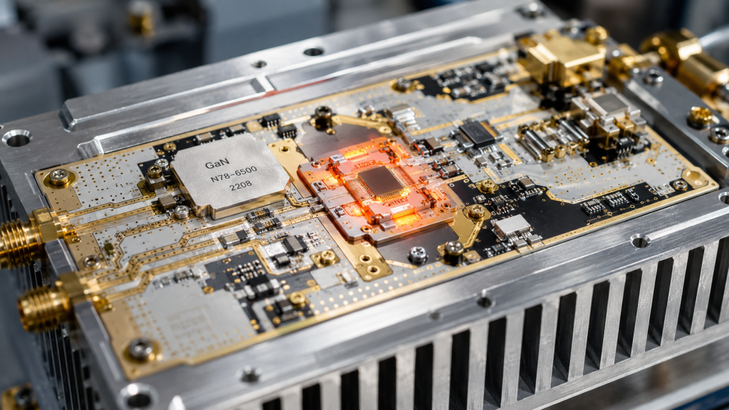
RF power amplifiers are inherently high-energy-consuming, non-linear devices. During continuous operation or when processing high-duty-cycle pulsed signals, the junction temperature (Tj) inside the RF modules rises rapidly. If the thermal dissipation boundaries—such as ambient temperature, heat sink thermal resistance, or the specific Cubic Feet per Minute (CFM) of forced air cooling—are not explicitly defined, the device faces an imminent risk of thermal runaway.
Furthermore, thermal interface materials (TIM) can suffer from “pump-out effects” under continuous thermal cycling if poorly designed, degrading the thermal path over time. In elevated temperature environments, the carrier mobility within the semiconductor material drops significantly. This physical phenomenon leads to severe gain drift and the rapid deterioration of linearity. In practical terms, this means that while an amplifier might successfully output the required field strength for the first ten minutes after power-on, its actual output power may drop well below the test standard’s baseline after a one-hour continuous EMC sweep.
3. Linearity, Signal Fidelity, and Pulse Droop
EMC testing frequently requires the amplification of specific modulated signals, such as AM, FM, or complex pulse waveforms. If the acceptance conditions only evaluate the saturated output power (Psat) under Continuous Wave (CW) conditions, while completely ignoring the 1dB compression point (P1dB) or the Intermodulation Distortion (IMD) metrics at various power back-off levels, the resulting RF energy will be contaminated.
Driving an amplifier deep into saturation without adequate linear headroom generates massive amounts of harmonics and spurious emissions. When this distorted signal is transmitted into the EMC chamber, the EMC receiver may misidentify these harmonic frequencies as actual interference points, rendering the entire system’s test data physically meaningless. Additionally, for pulsed RF applications, ignoring specifications like “pulse droop” will result in a failure to maintain signal amplitude across the duration of the pulse, directly failing aviation or radar immunity standards.
Establishing a Rigorous Procurement Acceptance Condition Checklist
To systematically eliminate the aforementioned risks, project managers and quality control teams must integrate the following core test conditions as mandatory engineering metrics into their Request for Quotation (RFQ) documents and procurement contracts. Furthermore, suppliers must be required to provide factory empirical test data corresponding directly to these specific conditions prior to delivery.
1. Explicitly Specify the Test Conditions for Output Power
Procurement documents must clearly define whether the nominal power is measured as Continuous Wave (CW) power or Peak Envelope Power (PEP). The distinction is critical, as a GaN architecture optimized for CW thermal loads differs fundamentally from one optimized for short, high-peak pulses. For wideband modules, you must require the supplier to provide power flatness test curves across the entire frequency band, explicitly rejecting data that only highlights the optimal test value at a single center frequency.
2. Mandate Environmental and Thermal Conduction Boundaries
All parameters related to gain and power must be strictly accompanied by their corresponding environmental temperatures (for example: tested at a +25°C baseplate temperature). Relying on ambient room temperature is insufficient; the thermal reference point must be on the hardware itself. Simultaneously, the direct current (DC) supply capabilities and power consumption margins of the system must be explicitly stated to ensure the power supply unit (PSU) can handle the PA’s current draw under maximum RF drive and thermal load.
3. Define the Trigger Logic for Protection Mechanisms
The exact activation thresholds for Over-temperature protection, Over-drive protection, Over-voltage protection, and VSWR protection/alarm functions must be mathematically quantified in the RFQ. Furthermore, the supplier must provide engineering proof that once the fault condition is removed (e.g., an antenna is reconnected or the ambient temperature drops), the protection mechanism will automatically recover normal operation, rather than resulting in irreversible hardware damage that necessitates an RMA.
Eliminating Acceptance Risks: Introducing the CorelixRF Standardized FAT Template
At CorelixRF, we strictly reject any performance promises that lack foundational physical data. To guarantee that project managers achieve a 100% first-pass system acceptance rate at the delivery site, we execute a stringent Factory Acceptance Test (FAT) protocol for every custom or standard platform project, providing our clients with highly transparent, traceable test records.
Consider our broadband solid-state RF power amplifier module, the CRF-PA-2000M26500M-6W, which is widely deployed in test and measurement instrumentation and EMC systems. When issuing the acceptance documentation for this specific model, the CorelixRF FAT template does not merely verify basic parameters; it explicitly locks down all physical conditions:
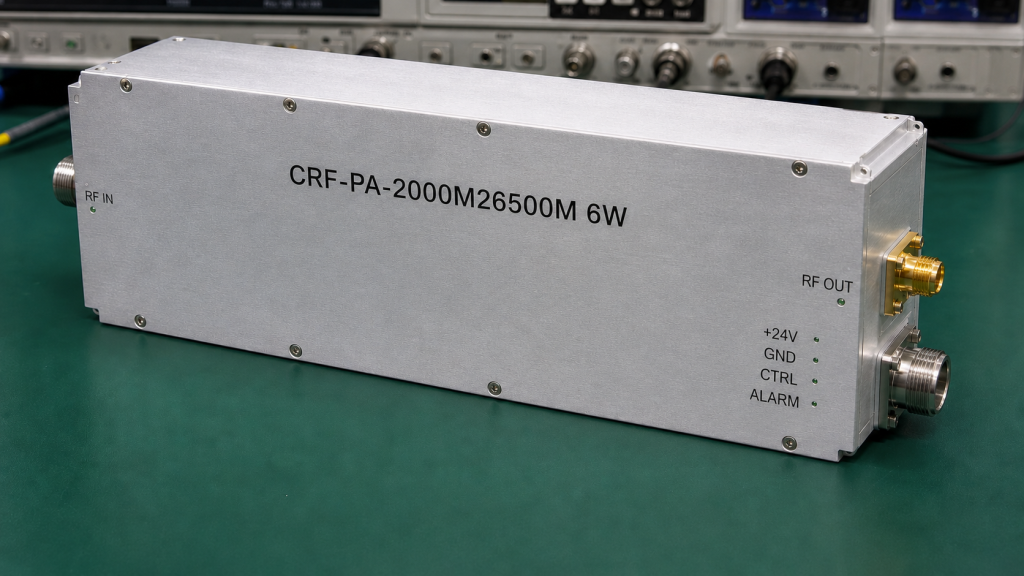
- Spectrum Coverage and Power Assurance: Operating within an ultra-wideband range of 2 GHz to 26.5 GHz, this module utilizes an advanced GaN architecture. Under a specified 50 Ω system impedance, it consistently delivers a 6 W rated output power alongside a 36 dB minimum small-signal gain. The FAT report provided to the client includes actual swept-frequency gain and power charts covering the entire band, actively proving the absence of power collapse at the frequency edges.
- Rigorous Empirical Testing of Protection Mechanisms: Our template explicitly verifies the built-in protection circuitry. Whether facing an over-temperature scenario, an input over-drive, or high VSWR reflections caused by mid-test antenna switching, the internal VSWR protection and alarm functions of the CRF-PA-2000M26500M-6W are documented to precisely intervene according to predefined logic. We test and record the exact threshold at which the amplifier protects itself, ensuring the safety of your front-end test system.
- Physical and Electrical Interface Constraints: We treat mechanical and electrical interfaces as critical acceptance criteria. The RF input/output connectors (2.92 mm-Female), the control interface (RS232), the precise mechanical dimensions (240 x 160 x 50 mm), and the DC supply requirements (18 V / 6 A DC) are all mandatory inspection items. Furthermore, we explicitly specify the Forced Air Cooling requirements in our FAT, verifying the module’s thermal stability during prolonged, continuous EMC scanning applications.
By adopting such an exhaustive, physics-based acceptance template, procurement and quality departments can minimize technical risks to near zero before the equipment is even packed for shipping. You are no longer verifying cold, exaggerated marketing figures; you are verifying objective engineering truths.
Standardize Your RF Project Acceptance Process Today
Securing a large RF amplifier order and ensuring the success of a complex integration project is never determined by the lowest catalog price. It is determined by comprehensive risk control and falsifiable engineering test data. Do not allow vague specifications and undefined physical boundaries to drag down your EMC integration project schedule.
To ensure that your team is fully equipped to handle technical audits from suppliers and to eliminate all blind spots in your next procurement cycle, take action now:
Please click here to download the CorelixRF official industrial-grade FAT/SAT acceptance standard template and engineering evidence package. Arm your procurement workflow with a standardized checklist of physical conditions, and ensure your quality control is built upon the solid foundation of objective engineering data.
Connect EMC test failures to acceptance evidence
When an EMC amplifier project fails late, the cause is often missing acceptance detail. Define frequency points, power margin, load condition, duty cycle, field-strength goal, thermal soak and report curves before the purchase order.
Recommended next step: send the operating band, target output power, duty cycle, thermal or load condition, control interface, protection behavior and required FAT documents. CorelixRF can review this EMC amplifier acceptance failure prevention requirement against standard amplifier platforms, RF front-end options and custom engineering constraints.