
In system-level EMC (Electromagnetic Compatibility) testing and RF interference projects, procurement departments and system integrators have long relied on imported RF power amplifiers. However, faced with tightening budgets and lead times stretching up to dozens of weeks, finding alternative solutions has become a mandatory requirement for engineering procurement.
Replacement, however, is never a simple BOM (Bill of Materials) substitution. The most critical risks for system integrators are: exaggerated specifications from suppliers leading to insufficient field strength, acceptance failures during system integration, and excruciatingly slow after-sales responses caused by distributor models. Bypassing empty marketing promises, this article examines how to reduce the replacement risks of EMC amplifiers through strict control of physical mechanisms, focusing on the engineering validation process (prototype testing and FAT).
Replacement Concerns: Why Do Consistent “Datasheet Specs” Lead to System Acceptance Failures?
When comparing datasheets, procurement engineers often find that the nominal power of low-cost modules appears identical to that of imported brands. However, once integrated into an EMC anechoic chamber, issues such as sudden output power drops or even complete module burnout occur. The root cause of these acceptance failures typically lies in discrepancies between underlying physical mechanisms and testing standards.
The primary factor is Impedance Mismatch and Voltage Standing Wave Ratio (VSWR). EMC testing frequently requires driving complex antennas across broad frequency bands, which generate extremely high reflected power at specific frequency points. Amplifier modules lacking effective VSWR protection are highly susceptible to catastrophic failure due to thermal runaway when subjected to these high VSWR conditions.
The second factor is the nominal confusion between Continuous Wave (CW) and Pulsed RF signals. Certain suppliers falsely list peak power under pulsed conditions as CW power. Consequently, when the amplifier operates continuously at full power, Gain Drift degrades severely, triggering over-temperature shutdown and ultimately forcing an interruption of the entire system-level test.
Prototype Validation: Rejecting Blind Replacement by Focusing on Core Physical Mechanisms
To eliminate these concerns, prototype validation must not be limited to measuring a maximum output value with a power meter at room temperature. It must verify the long-term stability of the amplifier under extreme physical conditions. Achieving high-quality engineering replacement requires rigorous scrutiny of underlying hardware mechanisms.
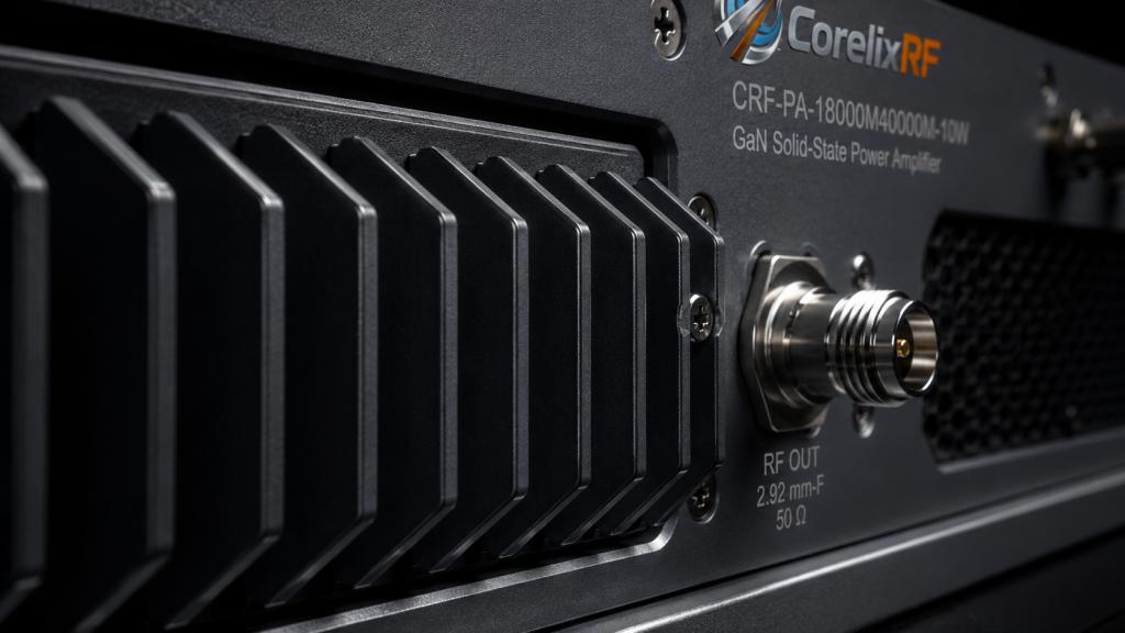
Take CorelixRF’s high-frequency module, CRF-PA-18000M40000M-10W, as an example. Based on an advanced GaN SSPA architecture, this module provides a rated output power of 10 W and a minimum small-signal gain of 40 dB across an ultra-broadband range from 18 GHz to 40 GHz. When conducting an engineering evaluation on such a unit, the following two points must be scrutinized:
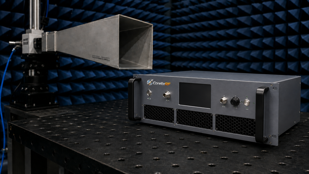
- Heat Flux Density and the Pump-out Effect: A 10 W RF output in the 18-40 GHz band implies massive heat dissipation requirements. If thermal interface materials are improperly selected, prolonged thermal cycling at high and low temperatures will cause the “pump-out effect” in thermal grease, exponentially increasing thermal resistance. Rigorous prototype validation must include continuous full-load fatigue testing on the underlying thermal architecture to verify its thermal stability.
- Comprehensive Protection Mechanism Validation: It is essential to verify whether the prototype is equipped with reliable over-temperature, over-drive, over-voltage, and VSWR protection alongside alarm functions. When input and output terminals (such as the 2.92 mm-F connectors equipped on this module) encounter extreme RF reflection, the hardware protection circuit must automatically respond within microseconds to reduce or cut off power, rather than relying on external heatsinks to “endure” the thermal stress.
Factory Acceptance Test (FAT): Establishing Trust Boundaries with Empirical Data
From standard platform models to customized project deliveries, the critical phase is strict quality control before shipment. Before placing volume orders for critical systems, procurement and quality departments must demand detailed Factory Acceptance Test (FAT) data reports from the RF manufacturing factory.
Blindly trusting product catalogs is highly risky. When delivering broadband power amplifiers like the CRF-PA-18000M40000M-10W, CorelixRF strictly adheres to the test specifications of the ISO 9001 quality management system. A qualified delivery FAT must include:
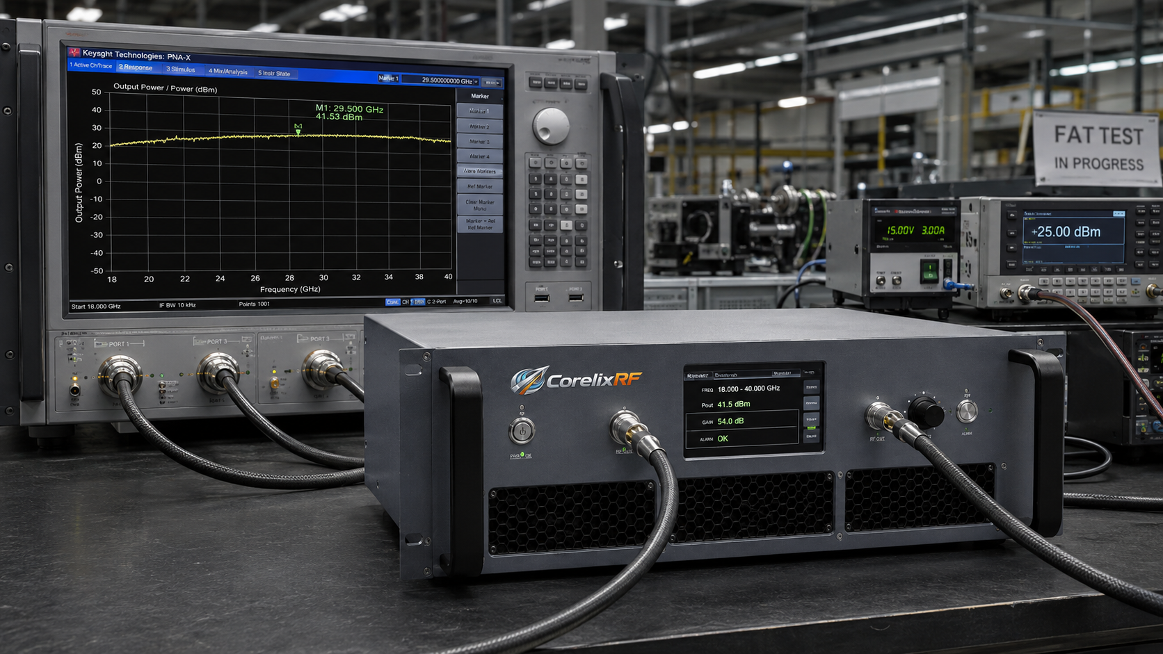
- Full-Band Output Power Curves: It is insufficient to show data only for specific center frequencies. Continuous swept-frequency test curves from 18 GHz to 40 GHz must be provided to prove the equipment does not suffer from power drop-outs or linearity collapse.
- Control and Monitoring Integration Records: Verification of whether the test equipment can accurately execute voltage and current status diagnostics and alarm feedback. For modules using a DC 18 V supply, communication control interfaces (such as CAN) must be capable of capturing any abnormal voltage fluctuations in real-time and outputting accurate engineering records.
- Mechanical Interference and Interface Tolerance Audit: Provision of precise mechanical drawings to confirm that physical dimensions (e.g., 250 x 150 x 100 mm) and RF connector locations strictly comply with the integration constraints of the system chassis, preventing on-site assembly failures.
SLA and After-Sales: Factory-Direct Support is True Industrial Added Value
Beyond aligning hardware metrics, the most easily overlooked aspect of replacing imported brands is the prolonged after-sales chain. When an imported module malfunctions, the overseas original manufacturer’s support chain is often hindered by cross-regional time zones and unprofessional distributors. This results in RMA (Return Merchandise Authorization) and repair cycles stretching for months, severely delaying project delivery nodes.
Introducing a domestic manufacturing factory equipped with foundational R&D and production capabilities offers core industrial added value through factory-level Service Level Agreements (SLA). Whether it is an initial engineering technical review for specific waveforms and duty cycles, or later-stage system integration, the CorelixRF engineering team can perform troubleshooting based on real physical hardware logic, providing immediate technical intervention to ensure the smooth closure of the acceptance process.
Conclusion
In the high-end RF and communication testing sector, finding a replacement for an EMC amplifier is a rigorous systems engineering task. Relying solely on rough parameters from a datasheet for replacement selection inevitably leads to extremely high acceptance risks. Only by delving into thermal design principles, verifying protection mechanisms, and relying on standardized FAT processes coupled with factory-direct SLA support can one truly achieve high-reliability, low-risk hardware substitution.
Reject parameter guesswork and ensure successful system delivery. Please submit your target frequency range, output power, operating mode (CW or Pulsed), and mechanical size constraints. CorelixRF senior engineers will provide a customized or platform-level technical solution based on empirical physical measurements within 48 hours.
Use EMC amplifier requirements as a procurement checklist
EMC replacement and immunity-test amplifier projects should confirm usable frequency range, field-strength target, load mismatch behavior, duty cycle, control method and calibration documents. A clear RFQ package helps us recommend whether an existing platform or a modified build is the better route.
Recommended next step: send the target band, output power, duty cycle, load condition, control interface, cooling limit and required FAT documents. CorelixRF can map this EMC amplifier replacement risk mitigation requirement to a standard platform or a controlled customization path.