
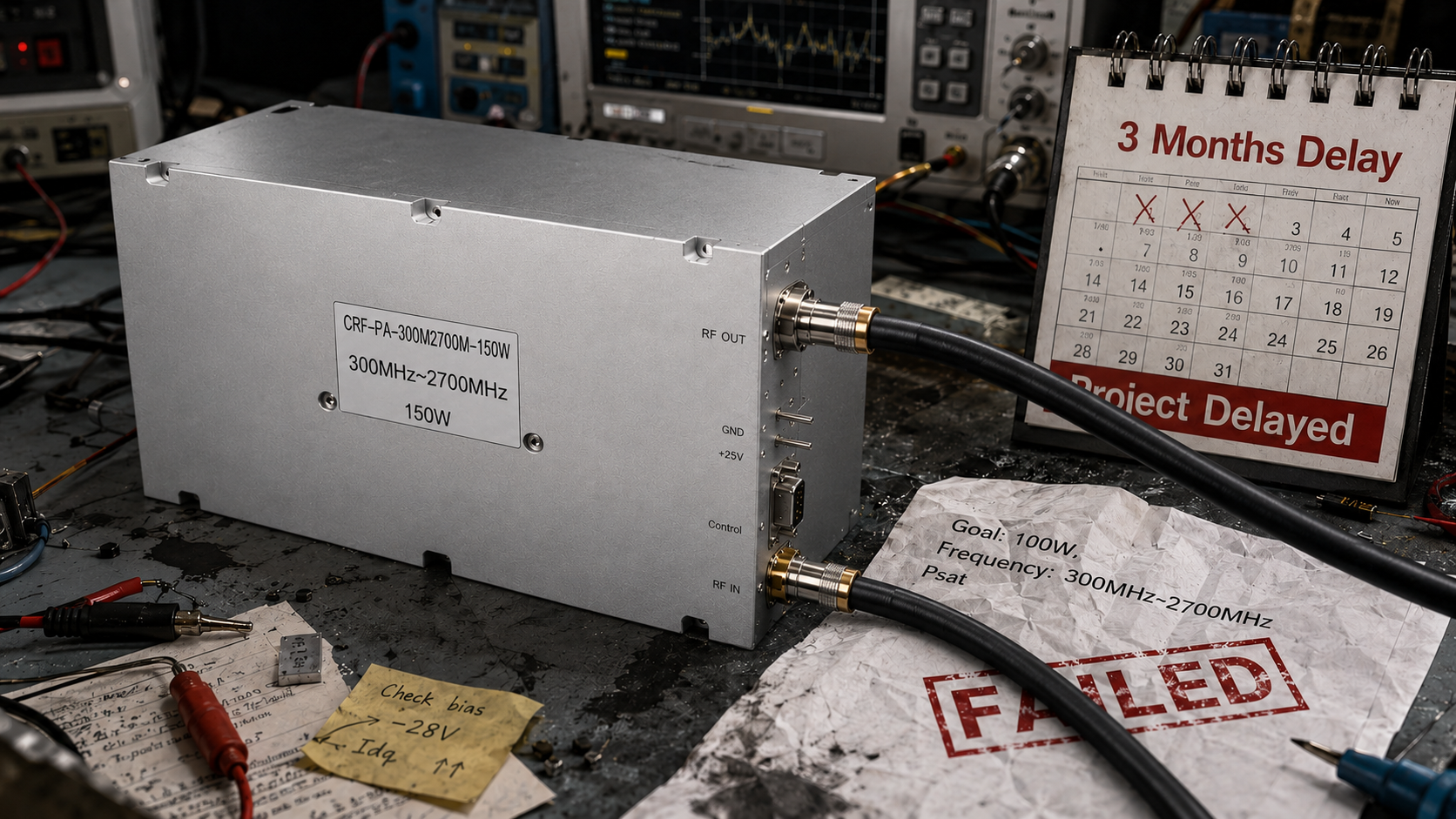
In the R&D and procurement process of Radio Frequency (RF) systems, one of the most fatal mistakes engineering teams and procurement departments make is using overly simplified Request for Quotation (RFQ) forms. Many procurement workflows solicit quotes from suppliers based solely on two single dimensions: “target frequency” and “saturated output power (Psat).” The direct consequence of this practice is that the equipment suffers severe thermal shutdown, gain drift, or even transistor burnout during Bench Tests or Site Acceptance Testing (SAT).
When an RF Power Amplifier (PA) fails system-level acceptance, the project faces months of delays. At this point, procurement contracts lacking clear engineering constraints often lead to suppliers shirking responsibility, making “slow after-sales service” an unsolvable deadlock. To completely eliminate the risk of suppliers “exaggerating parameters” and to ensure delivery acceptance passes on the first try, the only solution is to introduce a standardized RFQ template embedded with rigorous physical and electrical boundary conditions at the front end.
The Engineering Truth and Physical Mechanisms Behind Supplier “Parameter Exaggeration”
In the RF manufacturing industry, so-called “parameter exaggeration” is often not outright data falsification, but rather the exploitation of ambiguous testing conditions. The “maximum output power” listed on many commercial datasheets is measured under extreme, ideal laboratory conditions: a 50-ohm load, room temperature (25°C), and exclusively for Continuous Wave (CW) signals.
However, real-world radar, electronic warfare, or broadband communication systems are full of uncertainties. When an RF PA is connected to an actual antenna or system link, impedance mismatch is inevitable.
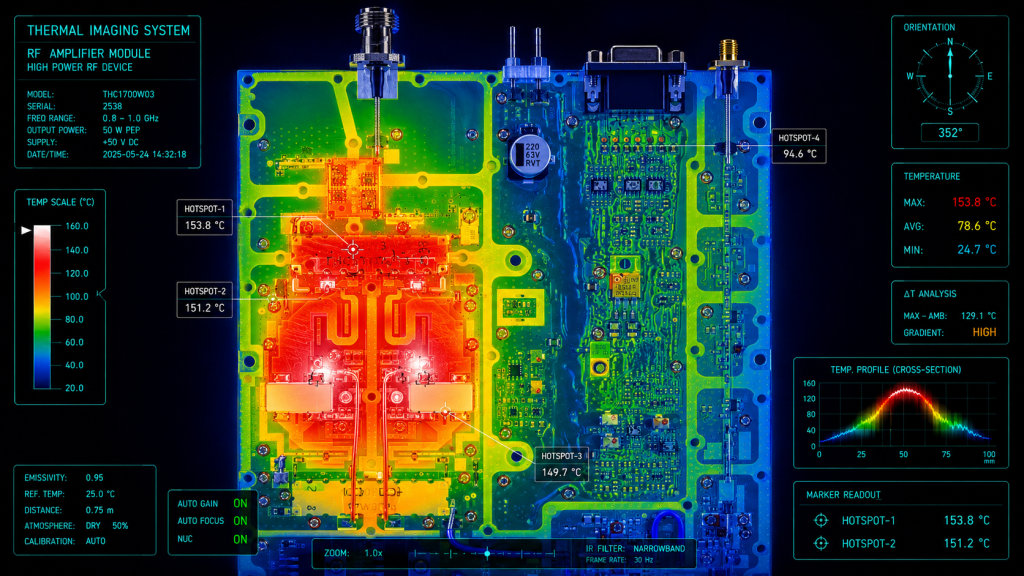
- Physical Mechanism Analysis: When a high Voltage Standing Wave Ratio (VSWR) occurs at the load end, the un-transmitted RF energy returns along the transmission line to the PA’s final-stage transistor as reflected power. This energy is directly converted into heat, causing the semiconductor device’s junction temperature (Tj) to spike dramatically.
- Engineering Risk: If the RFQ template does not explicitly mandate a “VSWR protection threshold under full reflection conditions” or “power foldback under a specific VSWR,” suppliers will typically provide low-cost modules lacking hardware protection circuits. Once antenna VSWR degrades in the field, the PA will quickly fail.
Linearity and Thermal Design Blind Spots: The Core Causes of Acceptance Failure
Beyond VSWR issues, another major disaster zone for procurement acceptance failure is the disconnect between the linearity requirements of modulated signals and the thermal dissipation design.
The Modulated Signal and Peak-to-Average Power Ratio (PAPR) Trap
Modern communications (such as OFDM) or complex radar waveforms have high peak-to-average power ratios. A PA that can output 100W under CW might enter a severe nonlinear region when outputting just 20W of a high-PAPR signal, leading to sharp degradation in Third-Order Intermodulation Distortion (IMD3) and Error Vector Magnitude (EVM). If the RFQ simply states “100W PA” without defining the test signal type and linearity metrics, the procured product will absolutely fail the final system-level communication tests.
Thermal Distribution and Gain Drift
As operating time increases and the baseplate temperature rises, the electron mobility of GaN or LDMOS transistors decreases, leading to reduced gain. Inexperienced procurement personnel often overlook thermal dissipation conditions in the RFQ. This results in PAs meeting standards during room-temperature testing but experiencing severe power drop-offs during burn-in testing inside high/low-temperature chambers.
Essential Fields for a Qualified RF PA RFQ Template
To ensure engineering alignment and properly constrain suppliers, a standardized RFQ template must be upgraded from a simple “commercial inquiry” to a strict “technical baseline.” An industrial-grade RFQ should contain at least the following engineering constraints:
- Core RF Parameter Boundaries: Explicit operating frequency band (e.g., 300 MHz to 2700 MHz).
- Power Definitions: Differentiation between P1dB (1dB compression point power), Psat (saturated power), and linear output power under specific IMD3 limits.
- Gain Specifications: Required in-band gain flatness and gain drift tolerances across the full temperature range (e.g., -40°C to +85°C).
- Interface Connectors: Clear input/output RF connector types (e.g., SMA-F / N-F).
- Environmental & Stress Constraints: Maximum system load VSWR (e.g., normal operation under 3:1 VSWR, no damage under open/short circuit conditions).
- Thermal Constraints: Defined cooling method (conduction cooling vs. forced air cooling) and maximum operating baseplate temperature requirements.
- Protection Logic: Requirements for hardware self-recovery protection against over-voltage, over-current, over-temperature, and high VSWR.
- Monitoring Interfaces: Definition of control/telemetry interfaces (e.g., D-Sub 15-Pin supporting PA_EN control timing, RS485 telemetry analog output).
CorelixRF’s Factory-Tested Evidence and Differentiated Delivery
At CorelixRF, we refuse to rely on polished marketing data. We insist on “Engineering Truth,” requiring all factory specifications to be absolutely supported by laboratory test data.
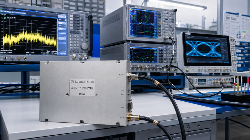
Take our broadband amplifier module CRF-PA-300M2700M-150W as an example. When a customer submits an RFQ containing detailed link constraints, our technical team does not quote blindly; instead, we initiate a rigorous engineering review within 48 hours. We align the module’s true test curves across the entire 300-2700 MHz band, its thermal distribution performance under various mismatch conditions, and the timing matching of hardware control interfaces.
To eradicate customer anxieties over “acceptance failure” and “after-sales buck-passing,” CorelixRF provides a complete Factory Acceptance Test (FAT) report with every delivered batch. This includes S-parameter sweep records for every single unit, high/low-temperature burn-in data, and thermal imager monitoring records at full power. Through transparent test evidence and clear Service Level Agreements (SLAs), we ensure that procurement and quality departments know exactly how the hardware will perform in the system before they even receive it.
Conclusion and Next Steps
The stability of an RF system is built upon the reliability of every microwave component. Do not let a vague RFQ become the fuse for project-wide delays. By introducing an RFQ template with strict engineering baselines, you can filter out unqualified suppliers at the source and ensure that your procurement funds translate into truly usable RF capabilities.
To help your engineering and procurement teams establish rigorous supplier admission and testing baselines, please take the following action immediately:
[ Download Information Package ] Get the official CorelixRF Standardized RF Power Amplifier RFQ Template and FAT Acceptance Checklist.
RFQ template to supplier review
Use the RFQ template to request measurable factory evidence
A useful RF amplifier RFQ template should not only list frequency and output power. It should make acceptance criteria, protection behavior, thermal limits, interface constraints and required delivery documentation clear before pricing.
Frequency range, output power, gain flatness, duty cycle, waveform, load/VSWR condition and pass/fail limits.
Protection response, thermal margin, calibration chain, connector/interface limits and operating environment.
Datasheet, measured data, FAT checklist, inspection records, delivery documentation and case-style review.
CorelixRF engineering review path: for RF amplifier RFQ preparation, connect the article findings to a manufacturable RF chain before requesting a quote. Review RF power amplifier options, compare the UHF amplifier path when low-band coverage is involved, check custom RF front-end integration, confirm the RF antenna interface, then send band, power, duty-cycle, protection and documentation needs through engineering inquiry.