
What Are RF Power Amplifier Acceptance Standards And RMA Processes?
Many project managers face major challenges during RF power amplifier procurement. A common mistake involves treating an ideal datasheet as absolute truth. This oversight often leads directly toward disastrous system integration failures later. CorelixRF engineers design objective testing protocols for verifying product reliability. What is the real story? We offer a clear path regarding factory acceptance testing. Our robust methodology establishes undeniable trust among global purchasing departments.
1. Why Do Typical Datasheet Specifications Cause Procurement Failures?
Procurement specialists must evaluate component limits rigorously before authorizing large orders. Suppliers frequently provide typical performance values measured within highly controlled laboratories. Such ideal environments rarely exist during actual field deployments or testing. You might be wondering: what causes these severe discrepancies during operation? An amplifier tested at room temperature behaves differently under heavy load. A liquid-cooled baseplate maintains ideal conditions easily during brief sweep tests. Your final radar system lacks those same luxurious cooling capabilities. Consequently, performance drops dramatically when integrated into tight equipment racks. Engineers notice major power loss during final site acceptance evaluations. Such degradation creates immediate disputes between buyers and hardware suppliers. Procurement teams need verifiable proof rather than optimistic marketing claims. Relying solely upon typical parameters guarantees integration delays down the line. You must demand hard data reflecting worst-case operational scenarios consistently. CorelixRF provides extensive documentation detailing exact limits under severe stress. Component buyers face immense pressure balancing budget constraints against technical requirements. Approving hardware blindly causes massive financial losses inevitably down the road. You must evaluate every performance chart skeptically before signing purchase orders. Vendors highlighting peak power figures hide severe limitations intentionally sometimes. These isolated peaks happen briefly under laboratory settings exclusively. Real systems demand sustained output holding steady across diverse environmental extremes. Ignoring these physical truths guarantees painful troubleshooting sessions later. Engineers spend valuable time chasing ghost issues caused directly by subpar amplification stages. Your team deserves reliable components delivering promised results under genuine stress. CorelixRF engineers understand these harsh realities perfectly. We test products emulating real deployment environments extensively.
Laboratory Setup Versus Field Deployment Realities
| Parameter | Controlled Laboratory Environment | Actual Field Integration |
| Ambient Heat | Maintained strictly around 25°C | Fluctuates heavily between -40°C and +70°C |
| Cooling Method | Massive heat sinks or liquid plates | Limited forced air utilizing confined chassis fans |
| Load Mismatch | Near perfect 50-ohm match | Antenna degradation causes high reflections constantly |
| Operation Time | Short duration swept testing | Continuous high duty cycle transmission |
2. How Does Thermal Drift Affect Output Power During Integration?
Solid-state amplifiers rely heavily upon stable semiconductor junction temperatures continuously. Gallium Nitride devices generate substantial heat during high-power signal generation. This is where it gets interesting: poor thermal management ruins efficiency. Elevated temperatures reduce electron mobility across microscopic transistor channel structures. This physical limitation causes immediate transconductance degradation within active components. System gain drops rapidly as internal chassis heat rises uncontrolled. Your driving stage can no longer push final transistors into saturation. The resulting power slump compromises entire communication array transmission ranges. Engineers refer directly toward this phenomenon as thermal gain drift. You cannot ignore basic thermodynamic laws governing modern semiconductor physics. CorelixRF tests every unit rigorously under forced air cooling conditions. We mandate strict compliance before authorizing any product shipment outwardly. Buyers receive definitive proof regarding thermal equilibrium performance characteristics always. Proper mechanical design prevents disastrous overheating failures during rigorous hardware testing. Cooling mechanisms dictate operational lifespans directly across modern RF designs. Standard datasheets assume perfect thermal sinking capabilities constantly. Your actual system chassis provides minimal airflow realistically. Heat accumulates quickly trapping dangerous thermal energy near delicate semiconductor junctions. Transistor performance degrades predictably following established physical thermodynamic principles. Active devices lose gain rapidly whenever baseplate temperatures exceed specified safety thresholds. Output signals distort heavily causing unacceptable data transmission errors across communication links. Preventing these thermal runaways requires massive engineering foresight initially. Buyers must request continuous wave testing records validating cooling efficiency claims. CorelixRF implements advanced forced air management techniques preventing catastrophic overheating incidents. We prioritize stable operation maximizing system uptime securely.
Thermal Impact On Key RF Parameters
| Condition | Small-Signal Gain | Saturated Output Power |
| Ideal Cooling | Stable baseline | Full rated specification |
| Moderate Heat | Marginal degradation | Slight compression drop |
| Severe Heat | Major loss | Fails acceptance criteria |
| Overheating | Drastic reduction | Triggers thermal shutdown |
3. What Is The Impact Of Impedance Mismatch On System Reliability?
Ideal test benches utilize perfectly calibrated loads presenting minimal reflection. Field antennas often exhibit severe voltage standing wave ratio degradation. But here is the kicker: mismatched loads destroy amplifiers instantly sometimes. Reflected energy travels backwards entering delicate final stage transistor networks. This reverse wave alters load lines disrupting proper current flow. Transistor drain voltage spikes dangerously beyond designed breakdown limits rapidly. Such extreme overvoltage conditions cause immediate permanent hardware destruction unfortunately. Many budget suppliers omit fast-acting protection circuits for saving costs. They leave your expensive infrastructure vulnerable against sudden antenna faults. CorelixRF integrates highly sensitive forward and reverse power monitoring systems. Our products trigger rapid protection algorithms preventing catastrophic internal damage. Procurement documents must specify mandatory load pull tolerance verification thoroughly. A reliable supplier demonstrates robust survival capabilities across mismatched conditions. Perfect antenna matches exist only inside textbook engineering examples. Real world systems experience shifting loads continually during active operations. Environmental factors alter impedance characteristics creating massive reverse signal reflections continuously. Without built in isolation mechanisms your amplifier absorbs this destructive energy fully. Internal voltages rise sharply exceeding component ratings within mere microseconds. Catastrophic failure follows instantly destroying expensive internal circuitry permanently. Replacing burned modules costs thousands delaying project timelines drastically. Smart procurement strategies require demanding internal protection validation actively. CorelixRF designs incorporate rugged directional couplers detecting mismatch conditions instantaneously. Our fast acting logic shuts down RF transmission protecting critical hardware. We prioritize survival under worst case scenarios preventing costly system replacements.
Hardware Protection System Trigger Thresholds
| Sensor Type | Operational Focus | Trigger Action Mechanism |
| Reverse Power | High VSWR monitoring | Rapid gain reduction |
| Thermal | Junction heat tracking | Automated RF disabling |
| Current | Transistor load sensing | Immediate power cutoff |
| Voltage | Supply level checking | Supply regulation adjustment |
4. How Can Factory Acceptance Testing Prevent Site Acceptance Failures?
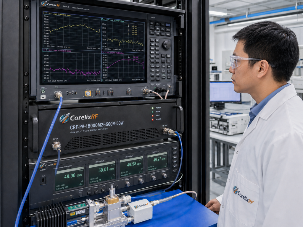
Blindly trusting preliminary qualification reports creates massive project execution risks. Every manufactured unit features slight physical variations affecting RF performance. A rigid factory acceptance test protocol eliminates devastating surprises later. Ready for the good part? You must demand serialized testing data. Spot checking frequencies fails revealing narrow band power dropout anomalies. Suppliers must execute continuous swept frequency evaluations across full bandwidths. They must operate equipment until reaching absolute thermal steady state. CorelixRF measures performance objectively after thirty minutes running continuous wave. We test our CRF-PA-18000M26500M-50W model strictly covering 18 GHz through 26.5 GHz. Our engineers record saturated output power rigorously exceeding 50 Watts. This rigorous verification establishes baseline confidence before final delivery occurs. Buyers must reject brief cold-start testing logs masquerading as proper validation. Proper acceptance procedures require documented evidence from worst case environments. Trusting vague marketing brochures invites severe project execution disasters consistently. Strict acceptance protocols establish concrete operational baselines verifying true hardware capabilities. Every shipped unit requires individualized testing records preventing future operational surprises. Demanding full frequency sweeps exposes hidden resonance problems effectively. Evaluating equipment strictly at thermal equilibrium uncovers hidden design flaws quickly. CorelixRF subjects every amplifier towards punishing validation cycles systematically. We verify small signal gain flatness strictly measuring within tight margins. Our engineers document power consumption carefully verifying strict system budget compliance. You receive detailed test packages confirming all promised parameters accurately. Refusing compromised testing shortcuts protects your professional reputation strongly. Thorough validation procedures separate reliable manufacturing partners from generic budget suppliers.
Required Factory Acceptance Testing Parameters
| Test Category | Methodology | Acceptance Criterion |
| Power Output | Swept frequency under load | Exceeds minimum ratings |
| Gain Flatness | Full band network analysis | Stays within tight decibel windows |
| Thermal Stability | Thirty minute full power burn | No severe transconductance drops |
| Hardware Protection | Intentional induced mismatch | Safe automated shutdown execution |
5. Why Do Standard RMA Procedures Take So Many Weeks?
Hardware failures happening during field integration halt entire engineering projects. Traditional return merchandise authorization processes drag slowly across several months. Here is the deal: manufacturers treat returned units like mysterious puzzles. Diagnostic technicians spend countless hours attempting failure replication on benches. Often they find nothing wrong because testing environments differ vastly. They return hardware labeling incidents as unverified customer operating errors. This frustrating cycle damages relationships destroying rigorous deployment schedules completely. The underlying issue remains poor diagnostic visibility inside legacy equipment. CorelixRF eliminates these opaque diagnostic loops using advanced digital telemetry. Clear data replaces subjective guesswork ending endless technical blame games. Modern supply chains demand rapid fault resolution maintaining operational readiness. We process warranty claims decisively based upon hard empirical evidence. Hardware failures cause immediate panic disrupting critical communication infrastructure significantly. Returning defective units triggers agonizingly slow bureaucratic investigation procedures normally. Engineers waste weeks waiting upon vendor diagnostic reports endlessly. Often the manufacturer blames external factors denying warranty coverage completely. You remain stuck holding broken equipment facing mounting project delays. Lacking objective operating data makes proving vendor fault nearly impossible technically. CorelixRF overhauls this painful process applying strict data driven diagnosis workflows. Our transparent approach eliminates subjective arguments fostering genuine collaborative problem solving. We analyze downloaded logs pinpointing exact failure modes rapidly. Faster resolution means your systems return online serving users properly again. We respect your schedule delivering definitive answers promptly.
Traditional Versus Telemetry Driven RMA Workflows
| Workflow Phase | Traditional RMA Methodology | CorelixRF Telemetry RMA |
| Fault Detection | Manual observation | Instant digital logging |
| Unit Return | Physical shipping required | Log file emailed instantly |
| Diagnosis | Weeks replicating issues | Hours analyzing raw data |
| Resolution | Lengthy dispute process | Rapid objective replacement |
6. How Does Telemetry Data Accelerate Fault Diagnosis?
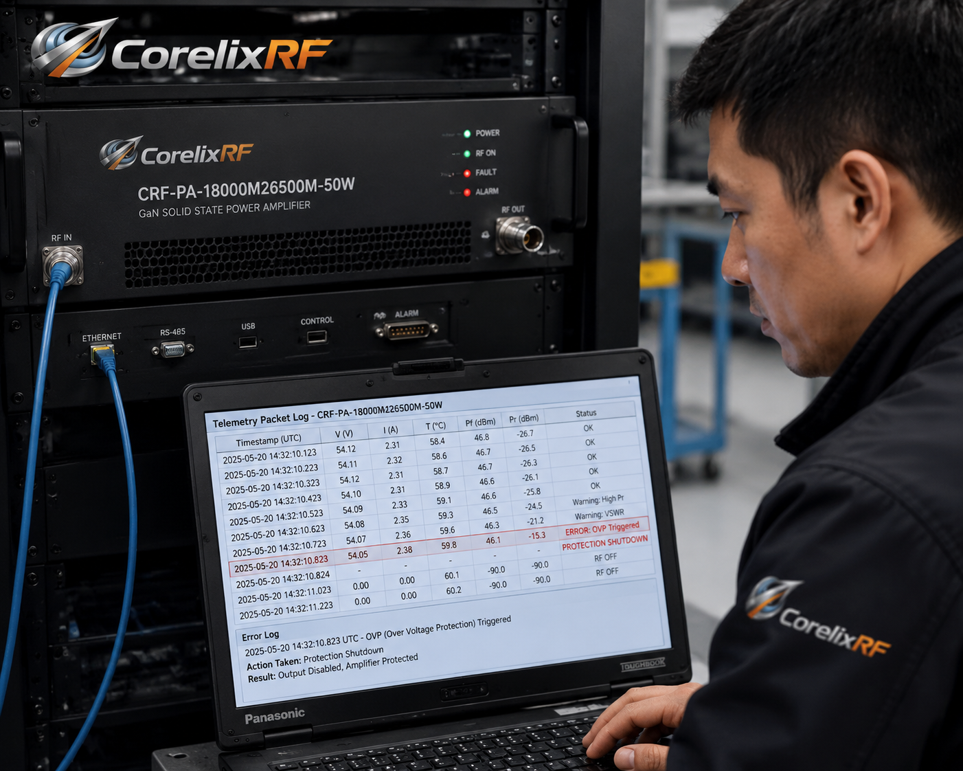
Modern industrial amplifiers contain sophisticated microcontrollers tracking critical health metrics. These built-in digital brains monitor voltages across every amplification stage. You might be wondering: how does this change maintenance workflows? A fault event triggers instantaneous logging storing exact operating parameters. Engineers download this logging history using standard Ethernet interface connections. The resulting file shows precisely what happened before system shutdown. If an external antenna shorted suddenly causing massive reverse power. The internal log proves this external fault caused protective disabling. This concrete evidence prevents vendor disputes regarding liability or misuse. CorelixRF promises preliminary failure analysis reports within forty eight hours. Our commitment relies totally upon these detailed internal diagnostic records. Project managers save weeks avoiding unnecessary shipping or prolonged testing. Digital telemetry transforms unpredictable repair tasks into predictable manageable steps. Smart hardware integration changes maintenance paradigms completely across aerospace industries. Incorporating sensitive digital monitoring circuits adds immense value toward system longevity. These sensors track internal voltages capturing transient anomalies perfectly. Real time monitoring prevents minor issues becoming massive catastrophic failures eventually. When protective shutdowns occur engineers possess exact historical operating snapshots instantly. They see exactly which parameter triggered internal safety algorithms accurately. Reviewing these logs reveals whether external systems caused unexpected power reflections. Data driven investigations replace costly blind troubleshooting methods entirely. CorelixRF supports standard digital interfaces integrating easily within larger control frameworks. We empower your technicians utilizing concrete evidence driving fast repair decisions. Telemetry turns unpredictable breakdowns into manageable scheduled maintenance events.
7. What CorelixRF Quality Assurances Benefit Procurement Teams?
We manufacture RF components applying uncompromising industrial quality control standards. Our production facility operates under strict ISO 9001 management protocols. This is where it gets interesting: compliance means documented transparency everywhere. CorelixRF never relies upon ambiguous typical values securing purchasing contracts. Every parameter cited originates directly from verifiable physical laboratory measurements. We support required CE and RoHS documentation requirements where applicable. Your compliance officers receive all necessary paperwork smoothing import customs. Each delivery includes detailed mechanical drawings assisting mechanical integration engineers. We build trust deliberately avoiding exaggerated marketing claims confusing buyers. Our objective engineering truth philosophy simplifies vendor qualification processes significantly. We encourage rigorous audits verifying our robust manufacturing testing capabilities. Global purchasing departments require absolute certainty qualifying new hardware vendors carefully. Our factory maintains rigorous internal auditing maintaining supreme manufacturing consistency daily. We supply detailed regulatory documentation supporting complex international shipping logistics perfectly. Design transparency remains our fundamental guiding philosophy across all engineering disciplines. You receive accurate mechanical dimensions preventing costly chassis redesigns later. We avoid using theoretical performance models securing final purchase agreements ever. Real measurements taken from actual production units dictate our guaranteed specifications. This straightforward communication style builds lasting trust among technical procurement teams. CorelixRF invites customer engineering teams reviewing our extensive laboratory validation setups actively. Seeing physical testing procedures firsthand reinforces our strong reliability commitments clearly. We stand behind every manufactured component delivering proven industrial performance.
8. How Does The CRF-PA-18000M26500M-50W Perform Under Stressed Conditions?
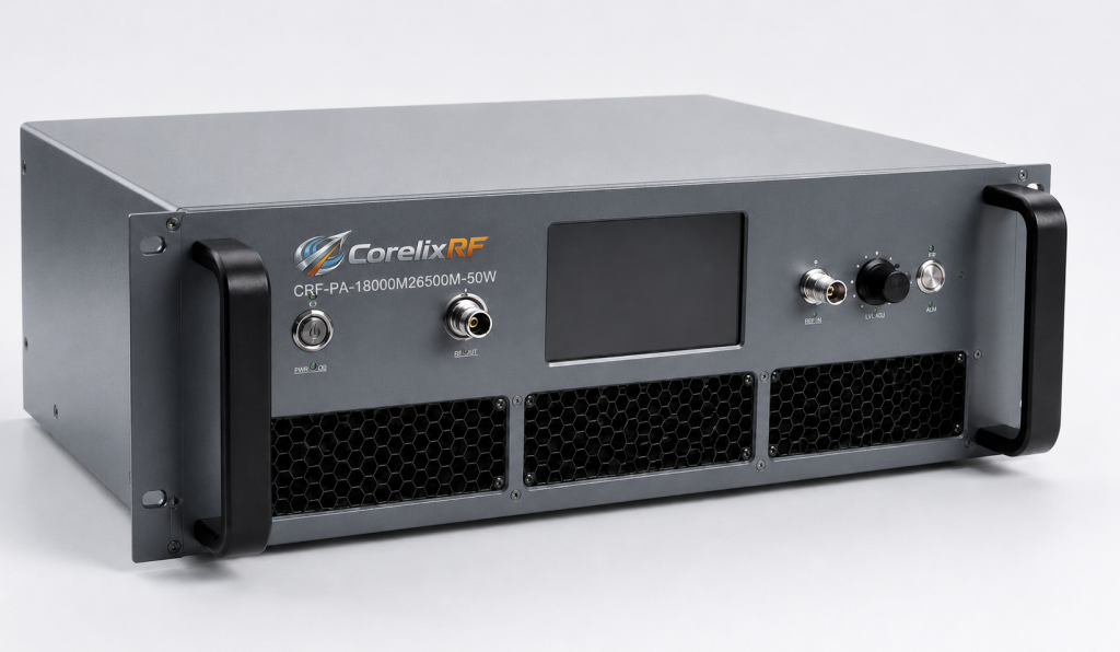
This specific solid state power amplifier targets highly demanding applications. It provides continuous millimeter wave coverage supporting test instrumentation systems. Ready for the good part? We guarantee fifty watts saturated power. The small signal gain measures minimum forty seven decibels reliably. Built inside a rugged chassis measuring 478 by 432 millimeters. It handles input power reaching zero dBm without sustaining damage. Operating temperatures span smoothly from zero until fifty degrees Celsius. CorelixRF integrates over temperature protection triggering at seventy five degrees. Mismatch survival handles VSWR levels reaching four to one safely. The unit consumes maximum seven hundred watts utilizing AC supply. We supply Ethernet alongside GPIB connections supporting smooth automated control. Every detail reflects conscious engineering prioritizing supreme reliability above all. Engineers designed this wideband platform supporting rigorous testing laboratory environments primarily. It drives aerospace control systems delivering reliable microwave signals consistently. The design incorporates robust WR42 waveguide output connectors handling high power. Input signals enter through precision standard coaxial interface ports securely. We test harmonic rejection keeping unwanted signals below twenty decibels. Spurious emissions remain tightly controlled preventing adjacent channel interference completely. The package weighs under fifteen kilograms easing rack mounting procedures significantly. Customization options include adding internal dual directional couplers measuring power accurately. We support specific control protocol requirements matching your exact project needs. This specific model represents our uncompromising dedication toward superior hardware engineering.
9. What Are The Necessary Steps For Validating A Solid-State Amplifier?
Engineers must verify performance boundaries meticulously securing long term stability. First establish baseline gain flatness across entire operational frequency ranges. Here is the kicker: minor ripples indicate severe matching network flaws. Measure harmonic distortion verifying spurious emissions stay below sixty dBc. Drive inputs progressively charting precise P1dB compression points under load. Record current consumption carefully identifying potential thermal runaway conditions early. Verify protective circuit response times introducing intentional high VSWR loads. CorelixRF documents these precise validation steps providing exhaustive test reports. Procurement professionals must mandate similar rigor reviewing competing vendor proposals. Accepting abbreviated datasheets invites disastrous failures during final system deployments. Thorough validation demands patience yielding highly predictable resilient RF infrastructure. Validating high frequency amplifiers requires specialized microwave measurement equipment properly calibrated. Technicians sweep entire frequency bands identifying subtle performance dropouts carefully. They monitor input return loss verifying stable source matching characteristics continually. High reflection levels indicate poorly designed internal matching networks immediately. Evaluating harmonic content verifies clean signal transmission maintaining spectrum regulatory compliance. Driving amplifiers beyond linear regions maps precise compression characteristics accurately. You must record internal temperatures validating heatsink design efficiency properly. CorelixRF performs all these critical steps internally before authorizing product shipments. We document results clearly providing undeniable proof regarding hardware capabilities. Purchasing managers utilizing these detailed reports eliminate risky integration variables completely. Careful validation methodology guarantees long term field operation success dependably.
10. How Do You Finalize A Secure RF Power Amplifier Purchase?
Purchasing high performance microwave hardware demands rigorous technical diligence always. Avoid suppliers relying primarily upon simulated models predicting field behavior. What is the real story? You need documented physical evidence absolutely. Draft contracts demanding full test data matrices before authorizing payments. Specify acceptable drift limits explicitly covering all anticipated environmental extremes. Establish firm service level agreements dictating rapid data driven RMA. Download our specialized procurement verification checklist reviewing complete vendor compliance. This resource pack includes standardized diagnostic terms protecting your investment. We designed these tools helping you manage integration risks effectively. CorelixRF remains dedicated advancing transparent industrial B2B hardware manufacturing practices. Protecting large infrastructure investments requires proactive vendor management strategies implemented early. Include strict testing requirements directly within initial request for proposal documents. Force suppliers quoting typical specifications translating those into minimum guaranteed values. Demand transparent diagnostic capabilities reducing future maintenance downtime dramatically. Review our provided checklist verifying every critical performance parameter thoroughly. Partnering with transparent manufacturers reduces hidden integration costs substantially. CorelixRF stands ready supporting your most demanding microwave engineering projects globally. Our data driven philosophy removes technical ambiguity securing your final purchase. We provide all necessary laboratory evidence building absolute confidence. Equip your procurement team utilizing our exhaustive engineering verification tools today. Superior RF systems begin by demanding objective manufacturing truth always.
FAQ
Q1: What is the main cause of amplifier integration failure?
Thermal drift causes severe gain reduction when internal chassis heat rises unexpectedly during continuous operation.
Q2: How does impedance mismatch affect solid state power amplifiers?
High reflection from mismatched antennas forces extreme voltage spikes potentially destroying final stage transistor components instantly.
Q3: Why are typical datasheet specifications unreliable for procurement?
Suppliers measure typical values under ideal liquid cooled laboratory environments rarely matching actual field deployment conditions.
Q4: How does telemetry data accelerate the RMA diagnostic process?
Built in sensors log critical operating parameters instantly allowing engineers rapid objective failure analysis without shipping delays.
Q5: What documentation must buyers demand during factory acceptance testing?
Procurement teams must demand continuous swept frequency power data recorded strictly after reaching thermal steady state equilibrium.