
In EMC (Electromagnetic Compatibility) radiated immunity (RS) testing projects (such as the IEC 61000-4-3 standard), one of the most common engineering errors made by laboratory facility builders or system integrators is directly equating the “saturated output power (Psat)” on the RF power amplifier (RF PA) datasheet with the actual radiated capability at the antenna end.
The results are often severe: at specific frequency points, the test field strength (V/m) in the anechoic chamber fails to meet the standard; or after 30 minutes of continuous swept-frequency testing, the process is forced to halt due to thermal degradation of the amplifier system. Such failures, exposed only during the on-site debugging phase, not only delay the overall acceptance cycle but also incur extremely high costs for subsequent after-sales troubleshooting. Relying solely on nominal parameters under an ideal 50Ω load is the root cause of EMC RF link integration failures.
The Underlying Physical Mechanism of Field Strength Non-compliance: Impedance Mismatch and VSWR Foldback
In a real EMC anechoic chamber environment, broadband transmitting antennas (such as log-periodic antennas or double-ridged horn antennas) can hardly maintain a perfect 50Ω impedance match across the entire broadband spectrum.
Reflected Power’s Impact on Forward Output
When the test frequency spans a large-bandwidth high-frequency band (for example, 2000 MHz to 6000 MHz), the Voltage Standing Wave Ratio (VSWR) at the antenna end easily deteriorates to 3:1 or even higher at edge resonant frequencies. At this point, the RF power amplifier will face severe reflected power feedback. To protect the internal final-stage power transistors (e.g., GaN HEMTs), many conventional commercial-grade amplifiers set very aggressive VSWR foldback protection mechanisms, forcibly reducing the forward output power once a slight mismatch is detected. This directly causes the effective field strength radiated onto the Equipment Under Test (EUT) to drop instantly, resulting in the direct failure of immunity testing at specific frequency points.
Continuous Operation Failure: Thermal Resistance Accumulation and Gain Drift
Standard EMC immunity testing typically requires the RF power amplifier to output Continuous Wave (CW) or Amplitude Modulation (AM) signals for a prolonged duration, with a single test cycle potentially lasting several hours.
Linearity Degradation Caused by Junction Temperature (Tj) Rise
If there are flaws in the amplifier’s underlying thermal management design or insufficient cooling margins, thermal resistance accumulation under high power output will cause the junction temperature (Tj) of the GaN transistors to rapidly approach critical limits (e.g., above 150°C). As the physical junction temperature rises, the RF amplifier will exhibit obvious gain drift and gain compression. In laboratory measured data, this manifests as: the amplifier can output sufficient power during the first 10 minutes of operation, but after 30 minutes of continuous use, the output power may naturally decline by 1 dB to 2 dB. For EMC laboratories with extremely strict field strength tolerance requirements, this power degradation is enough to invalidate all long-term test results.
The Black Box Dilemma of After-Sales Troubleshooting: Lack of Diagnostic Monitoring Data
Once a system experiences non-compliant field strength, system integrators often fall into a cycle of guesswork: “Is it an antenna matching problem, excessive coaxial cable loss, or a fault in the amplifier itself?” An amplifier lacking a real-time working status diagnostic interface is essentially a “black box” in actual engineering. Engineers cannot read critical data such as forward power, reverse reflected power, internal transistor temperature, and supply current in real time, making on-site fault isolation extremely difficult and drastically reducing after-sales response efficiency.
CorelixRF Application Case and Factory Empirical Evidence
In a recent third-party EMC laboratory upgrade project, the client required maintaining stable, high-field-strength continuous radiation testing within the 2000 MHz to 6000 MHz frequency band. The general-purpose amplifier previously purchased by the client frequently experienced field strength “dips” and thermal protection shutdowns in high-frequency bands like 4500 MHz due to unreasonable protection threshold settings.
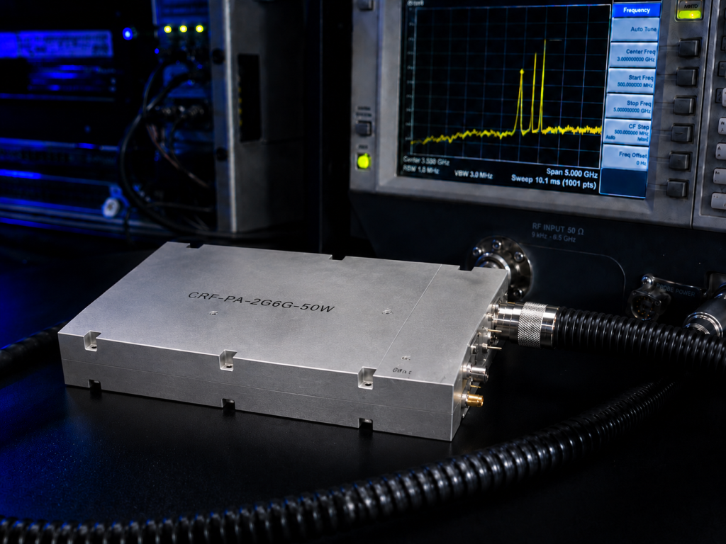
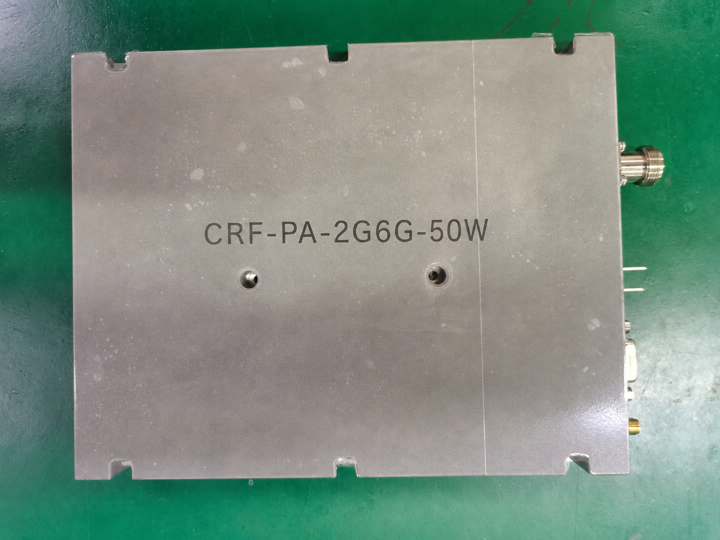
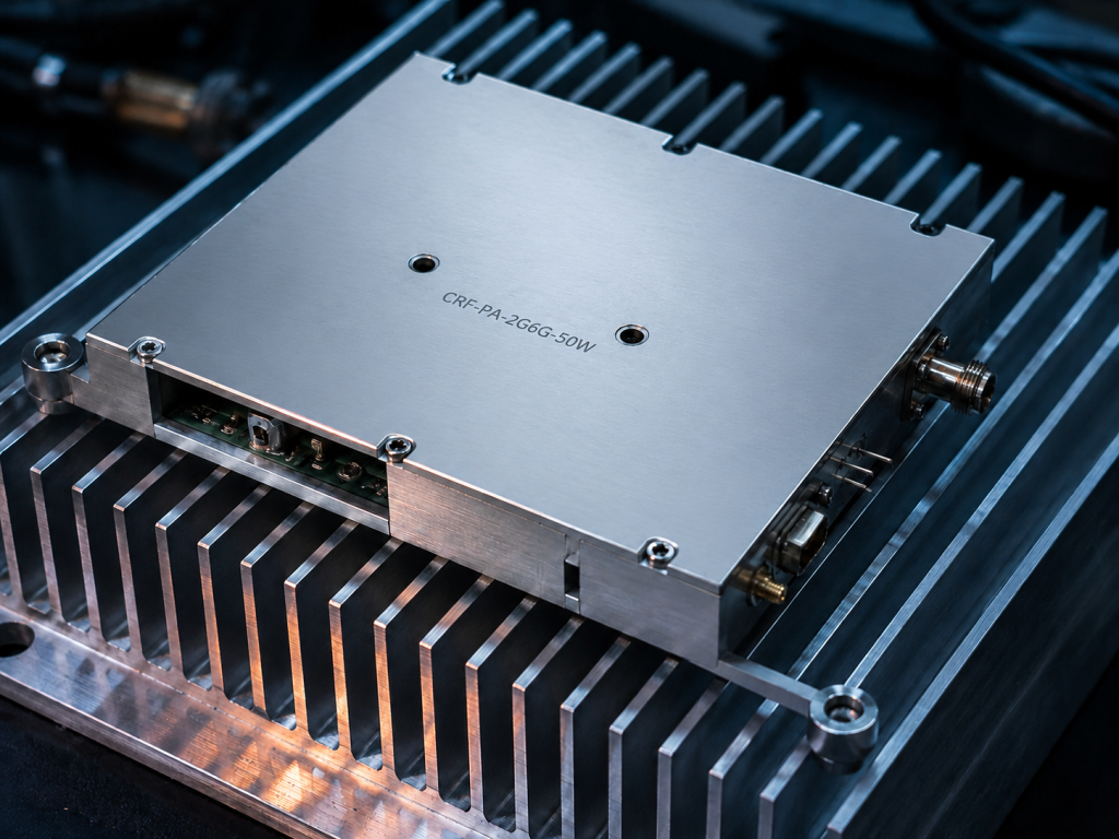
After rigorous engineering evaluation, we configured the CRF-PA-2000M6000M-50W broadband solid-state power amplifier module for this RF link. To resolve the pain points of field strength and continuous operation, CorelixRF provided rigorous factory empirical evidence before delivery:
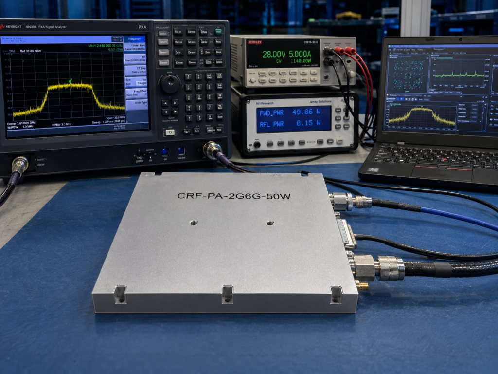
- Extreme VSWR Tolerance Verification: In the factory laboratory, we connected a mismatched load (VSWR ≥3:1) to the amplifier output for full-band swept-frequency testing. This verified that the PA can still maintain sufficient forward power output without triggering abrupt power reduction foldback, ensuring no dead zones in chamber field strength from a physical level.
- Long-Term Continuous Wave (CW) Aging Test: Provided gain stability data for 72 hours of continuous operation under full power, proving that the module’s thermal design, combined with an external heat sink, can strictly control the gain drift of long-term operation within the safety threshold required by engineering, eliminating mid-test power slides.
- Transparent Underlying Data Interface: The module is equipped with a D-Sub 15-Pin control interface supporting RS485 protocol communication. The client’s main console can capture forward/reflected power, internal temperature, and current alarm data in real time. When implementing on-site acceptance, system integrators can immediately define the physical boundaries between the amplifier and other link components, shortening after-sales diagnostic time from days to minutes.
Procurement Advice: Replace Single Parameters with Engineering Evidence
When procuring RF power amplifiers for EMC test systems and laboratory benches, the acceptance standard must be upgraded from “reading ideal parameters on a datasheet” to “reviewing system-level physical empirical evidence.” Without Factory Acceptance Testing (FAT) and Site Acceptance Testing (SAT) strictly based on real working scenarios, any power metric commitment lacks practical engineering significance.
Do not let your next EMC system integration project expose risks only during the on-site field strength calibration phase. Explicitly defining acceptance clauses for VSWR tolerance and continuous operation gain stability is the only path to guarantee successful project delivery.
👉 [Download the CorelixRF RF Power Amplifier FAT/SAT Acceptance Test Plan Template] Obtain the standard verification checklist used by professional procurement and quality engineers to mitigate delivery risks.
👉 [Schedule a 48-Hour Engineering Review] Submit your system test field strength, frequency band, and environmental constraint metrics, and let the CorelixRF RF technical team with decades of experience provide you with a customized module boundary confirmation and selection plan.