
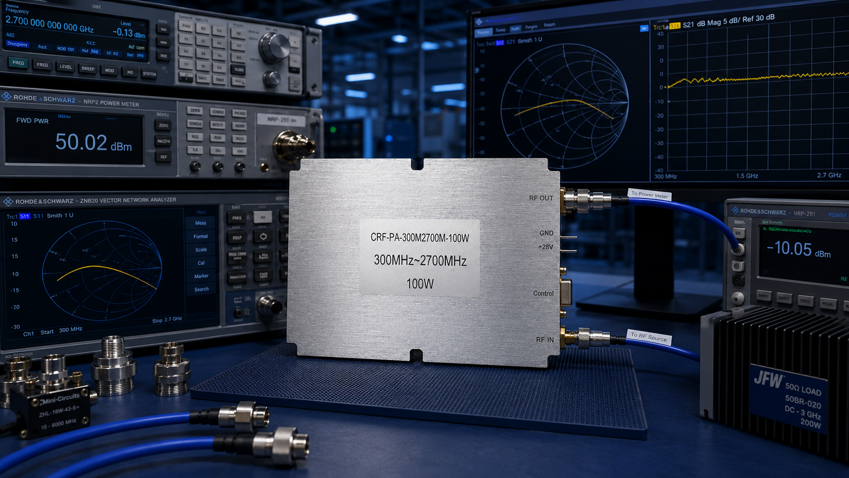
For research teams, academic laboratories, and system integration engineers, procuring an RF power amplifier (RF PA) often presents a recurring dilemma: working within strictly constrained budgets while navigating dynamic, unpredictable experimental conditions. Many R&D teams purchase standard commercial off-the-shelf (COTS) amplifiers based entirely on the ideal parameters listed in a product datasheet. However, once integrated into an actual test chain—whether for plasma excitation, magnetic resonance imaging (MRI), or driving non-standard antenna loads—the amplifier may shut down due to a Voltage Standing Wave Ratio (VSWR) alarm within minutes, or worse, suffer catastrophic failure at the final-stage transistors.
The root cause of this project failure is rarely a manufacturing defect in the amplifier itself. Instead, it is a severe misalignment between the actual physical conditions of the test bench and the nominal physical boundaries under which the amplifier was calibrated at the factory. In RF engineering, the failure to accurately evaluate load impedance, peak-to-average power ratio (PAPR), and thermal attenuation mechanisms remains the single largest risk for selecting the wrong model and overrunning project budgets.
The Physics of Impedance Mismatch and VSWR-Induced Catastrophic Failure
In an applied R&D environment, the RF load is rarely a perfect 50-ohm match. When the impedance of an antenna, a test cavity, or an experimental plasma chamber fluctuates dynamically, it generates an excessively high Voltage Standing Wave Ratio (VSWR).
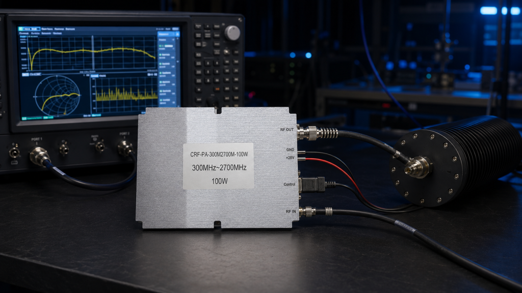
The nominal output power listed on a standard datasheet (for example, 100 W) is strictly measured under an ideal 50-ohm load condition. When the VSWR reaches 3:1 or higher, up to 25% of the RF energy is reflected from the load back into the final amplification stage of the PA. This reflected power cannot be converted into useful radiated energy or drive power; instead, it is dissipated entirely as heat. This process causes the junction temperature (Tj) of Gallium Nitride (GaN) or LDMOS transistors to spike exponentially.
Budget-constrained R&D projects often lean toward purchasing bare RF modules that lack comprehensive internal protection circuits. If the amplifier architecture does not include an RF isolator or a high-speed reverse power detection and VSWR protection loop, this rapid heat accumulation will lead to thermal breakdown of the semiconductor devices within milliseconds. Engineers must evaluate whether the PA can physically survive the specific reflective conditions of their laboratory setup, rather than assuming 50-ohm behavior.
Linearity, Saturation Power (Psat), and the Engineering Trap of Signal Distortion
Scientific applications—particularly those involving Software-Defined Radio (SDR) communications, Orthogonal Frequency-Division Multiplexing (OFDM) waveforms, or high-order Quadrature Amplitude Modulation (QAM) signals—demand exceptional signal fidelity. A critical engineering fallacy occurs when engineers equate the saturated output power (Psat) on a datasheet with the actual usable power for their specific waveform.
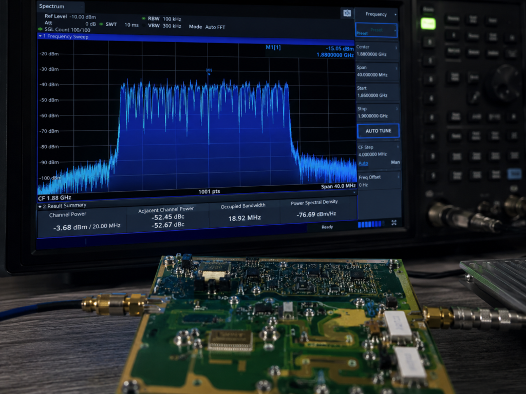
- Saturation Power (Psat): At this point, the amplifier is operating deep within its non-linear region. Gain is severely compressed. While the amplifier is outputting maximum RF energy, the waveform has undergone severe distortion.
- 1dB Compression Point (P1dB): This is the critical metric for linear operation. For complex modulated signals characterized by wide bandwidths and high PAPR, the operating point must be backed off several decibels below the P1dB threshold to prevent intermodulation distortion (IMD) and spectral regrowth.
If your SDR system requires 50 W of linear transmission power, and you purchase an amplifier with a rated Psat of exactly 50 W, you will encounter severe signal clipping, high error vector magnitude (EVM), and a soaring bit error rate (BER). The objective engineering approach dictates calculating the exact peak-to-average ratio of your waveform and reserving adequate power headroom to maintain strict linearity.
Gain Drift and the Hidden Costs of Inadequate Thermal Management
During sustained Continuous Wave (CW) full-power experimental runs, the baseplate temperature of the amplifier will inevitably rise. The fundamental physics of semiconductor devices dictates that gain decreases as the junction temperature increases. This phenomenon is known as gain drift.
If an amplifier supplier only provides “cold state” pulse test data—typically measured over a few dozen seconds in a controlled environment—the actual continuous output power during a multi-hour thermal experiment could degrade by 1 to 2 dB. This thermal attenuation makes experimental results impossible to replicate consistently. When evaluating an RF PA, engineers must demand empirical thermal stability curves tested at the maximum nominal operating temperature under full load conditions, rather than relying on instantaneous peak figures captured at room temperature.
A Rigorous, Physics-Based Workflow for RF Amplifier Selection
To prevent project delays and wasted capital, R&D engineers should avoid blindly ordering from catalogs and instead implement a selection protocol based entirely on physical boundary conditions:
Step 1: Define Physical Constraints and RF Boundaries
Before submitting any procurement request, define the exact laboratory conditions:
- Actual Load Characteristics: Estimate the maximum VSWR fluctuation range during the experiment (e.g., will the amplifier face open-circuit or short-circuit level extreme reflections?).
- Signal Waveform: Is the drive signal a single-frequency CW, a pulsed signal (requiring defined duty cycles and pulse widths), or a broadband modulated signal with high PAPR?
- Thermal Dissipation Capability: Does the laboratory facility provide liquid cooling infrastructure, or does the application strictly require an amplifier equipped with a dedicated forced-air cooling system?
Step 2: Demand Empirical Laboratory Test Data
Do not finalize decisions based on a sparse, single-page datasheet. A qualified RF manufacturing facility must be able to provide empirical evidence corresponding to the required frequency bands, including:
- Small-signal gain flatness curves swept across the entire operational frequency band.
- Measured P1dB and Psat charts recorded at various frequency points.
- Documented response times of the VSWR protection mechanisms under specific mismatch conditions.
Step 3: Shift from Standard Catalogs to Engineered Platforms
In complex RF systems, there is no universal, one-size-fits-all solution. Through decades of manufacturing, CorelixRF has established that the most reliable delivery pathway utilizes mature, standardized hardware platforms that are systematically fine-tuned for specific experimental conditions.
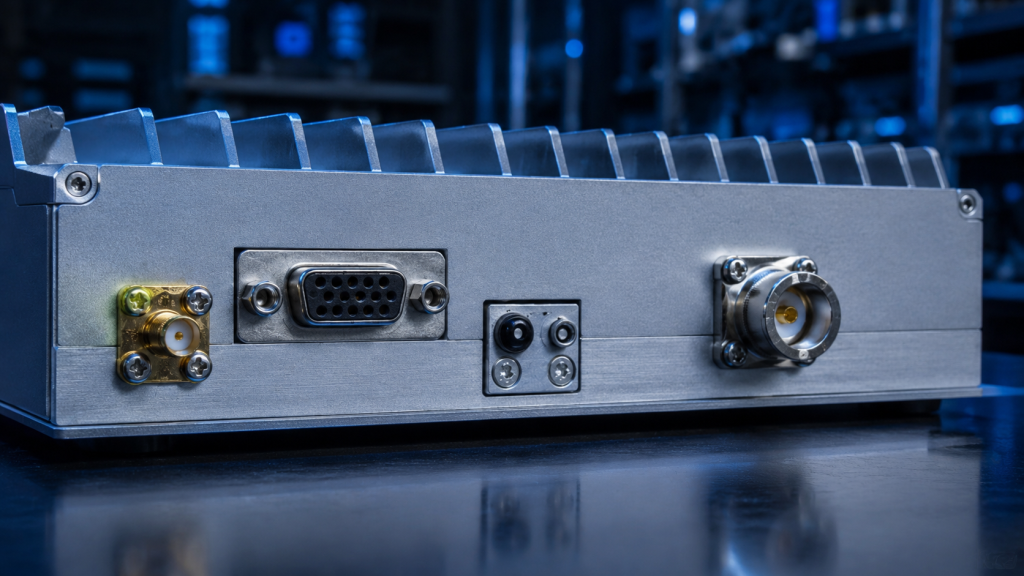
For instance, addressing broadband testing and system-level integration, the CRF-PA-300M2700M-100W solid-state power amplifier platform covers the core frequency band from 300 MHz to 2700 MHz, delivering 100 W of continuous wave (CW) output. However, for a specific R&D project, this platform allows our engineers to adapt the D-Sub 15-Pin control interface definitions, enabling the RS485 protocol for real-time monitoring of temperature, VSWR, voltage, and current. This delivery model—utilizing a standard hardware baseline, integrating necessary physical protection mechanisms, and subjecting the requirement to a thorough engineering review—minimizes experimental risk.
Secure Your Project with a 48-Hour Engineering Review
In the domain of RF testing and R&D, utilizing a constrained budget for trial-and-error procurement is an unacceptable risk. A datasheet with perfect parameters does not guarantee stable operation on your test bench.
To ensure the amplifier you procure perfectly matches your experimental physical boundaries, clear all technical ambiguities before issuing a purchase order. Map out the exact gain, power back-off requirements, and expected load VSWR conditions of your current RF chain.
Ready to eliminate uncertainty from your next RF experiment?
👉 [Submit your RFQ parameters and schedule a free 48-hour engineering review with CorelixRF]. We will utilize empirical factory test data to provide an objective, risk-free selection plan tailored to your laboratory setup.
From selection article to RFQ specification
If this topic matches your project, convert it into an RFQ before comparing suppliers. CorelixRF can review operating band, power definition, gain, linearity, waveform, duty cycle, VSWR risk, thermal environment, control interface and FAT requirements.
- Compare RF power amplifier platforms for standard and custom requirements.
- Use the RFQ checklist to prepare a complete request.
- Check delivery documentation for test records and acceptance evidence.
- Review case studies or contact CorelixRF for engineering review.
CorelixRF engineering review path: for RF power amplifier selection beyond datasheets, connect the article findings to a manufacturable RF chain before requesting a quote. Review RF power amplifier options, compare the UHF amplifier path when low-band coverage is involved, check custom RF front-end integration, confirm the RF antenna interface, then send band, power, duty-cycle, protection and documentation needs through engineering inquiry.