
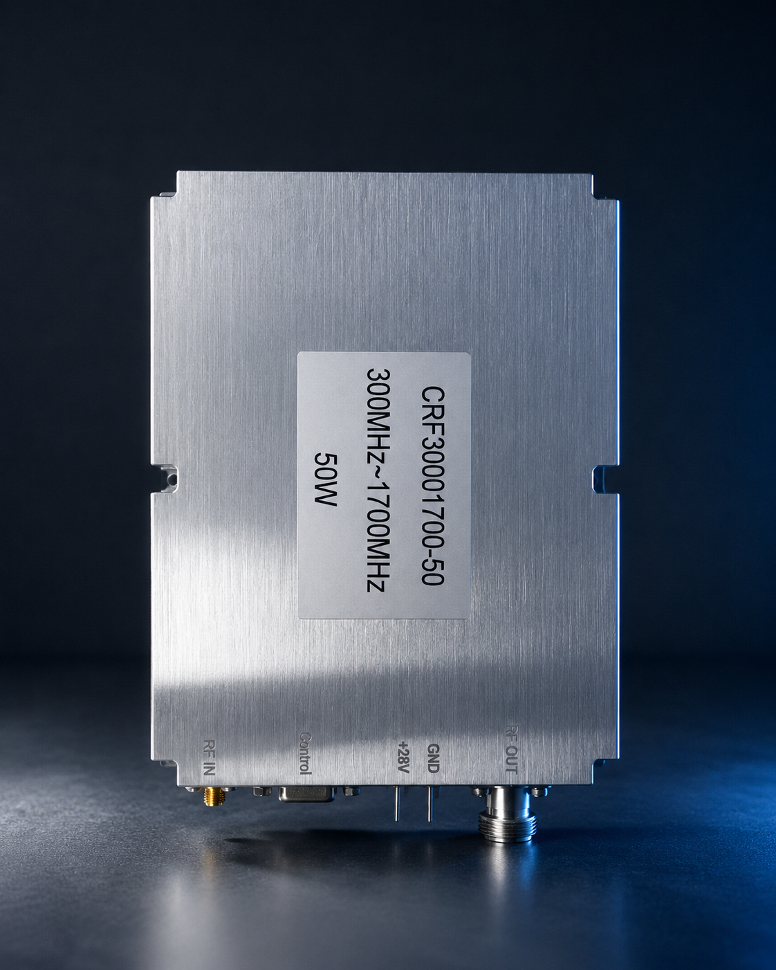
For procurement and quality assurance (QA) teams managing radio frequency (RF) radar, electronic warfare (EW), or advanced communication systems, the most common engineering nightmare typically occurs during laboratory bench testing or system integration: the newly procured RF power amplifier (PA) fails the Factory Acceptance Test (FAT) or Site Acceptance Test (SAT).
Many supplier datasheets appear flawless under ideal conditions. However, in actual system integration, when subjected to complex constraints such as high voltage, extreme voltage standing wave ratio (VSWR), or long-duration continuous operation, the equipment frequently experiences thermal shutdown, severe gain drift, or even direct destruction of the RF transistors. This “specification inflation” and the ambiguity of acceptance standards not only cause project delays lasting several months but also lead to prolonged post-sales responsibility disputes.
This article strips away all marketing rhetoric and returns to standard “Engineering Truth.” Based on underlying physical and engineering mechanisms, we will break down the 5 core acceptance clauses you must explicitly list in your contracts when procuring an RF power amplifier, along with the correct procedure for establishing standardized FAT/SAT protocols.
Why “Perfect” Datasheets Cannot Guarantee Acceptance
In the RF hardware manufacturing sector, parameters can often be “optimized” by restricting test conditions. For instance, an amplifier labeled as “50W” that is only tested under a 1 ms pulse width and a 1% duty cycle possesses a fundamentally different thermal design and GaN (Gallium Nitride) device architecture compared to one required to deliver a 50W continuous wave (CW) full-power output at a +60°C ambient temperature.

Without a deep understanding of the physical boundaries of impedance mismatch, thermal resistance dissipation, and intermodulation distortion (IMD), procurement departments cannot identify the systemic risks hidden behind standard specification sheets.
The 5 Core Acceptance Clauses for RF Power Amplifier Procurement
To prevent delivery and acceptance failures, procurement and QA departments must define the following acceptance checklist and testing methodologies in their procurement contracts and technical agreements. This is also the core reason why CorelixRF insists on conducting front-end engineering reviews with clients.
Clause 1: Survivability and Protection Mechanisms Under Extreme VSWR
Why it matters: In real-world field environments (such as a damaged antenna or a disconnected RF cable), impedance mismatch at the antenna end generates massive reflected power. This reflected energy travels back through the RF chain, causing the VSWR at the terminal transistors to spike rapidly, which in turn triggers avalanche breakdown. Template Example & Acceptance Standard:
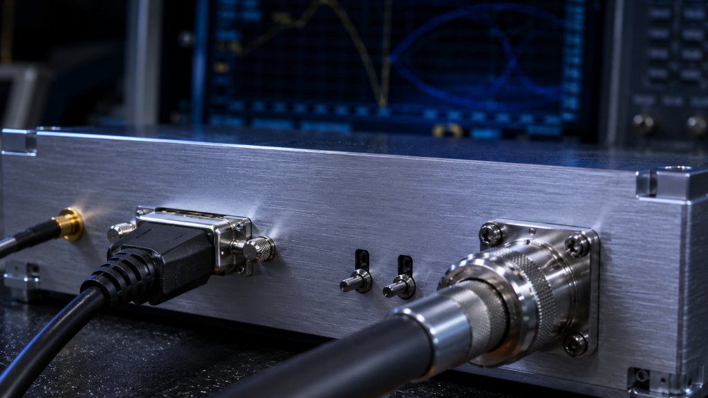
- Acceptance Requirement: The equipment must trigger internal isolation or VSWR protection circuits without sustaining permanent physical damage when subjected to full reflection (i.e., an open or short circuit, where VSWR is infinite) at maximum output power.
- Factory Test Evidence: CorelixRF conducts rigorous VSWR protection threshold testing prior to shipment. The FAT report must include the precise time (typically cutting off output at the millisecond level) required to trigger the protection mechanism under the rated voltage (e.g., +28V DC).
Clause 2: Continuous Wave (CW) Power and Gain Drift Boundaries at Thermal Equilibrium
Why it matters: Power specification inflation is the industry’s biggest minefield. The design of the heat sink and the management of the semiconductor junction temperature dictate whether the PA is only built for a “quick benchmark test” or if it can execute 72-hour uninterrupted missions. As temperatures rise, inadequate thermal resistance design will result in significant gain drift and power collapse. Template Example & Acceptance Standard:
- Acceptance Requirement: Specify a mandatory continuous wave (CW) full-load burn-in test of at least 24 hours at the maximum operating ambient temperature (e.g., +60°C). The gain degradation at any frequency point within the band must not exceed 0.5 dB.
- Factory Test Evidence: Taking the standard CRF-PA-300M1700M-50W as an example, the supplier must provide a comprehensive thermal imaging record and a long-term power stability curve for the module outputting 50W CW across the 300 MHz to 1700 MHz band, rather than a single instantaneous test screenshot.
Clause 3: In-Band Gain Flatness and Instantaneous Bandwidth Data
Why it matters: Wideband RF systems (such as SDR or OFDM signal amplification) are extremely sensitive to performance at the band edges. Some suppliers use narrow-band tuning to achieve very high gain at the center frequency, resulting in severe out-of-band attenuation and poor linearity. Template Example & Acceptance Standard:
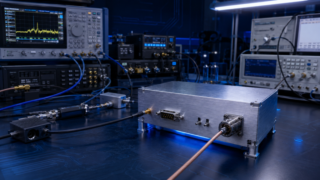
- Acceptance Requirement: Within the specified frequency range (e.g., 200 MHz instantaneous bandwidth), the small-signal gain must remain stable within the strict physical interval of 38 dB to 48 dB, with in-band gain flatness fluctuations not exceeding ±1.5 dB. All testing must be conducted under a nominal 50 Ω system impedance.
Clause 4: Strict Definition of Control and Interface Logic Boundaries
Why it matters: System integrators frequently encounter debugging failures because the main control board’s handshake with the PA module fails due to ambiguous enable-level logic definitions or mismatched interfaces. Template Example & Acceptance Standard:
- Acceptance Requirement: Acceptance documents must map pin definitions and response times one-to-one. For example, in a D-Sub 9-Pin interface, Pins 1-4 are VDD, and Pin 8 is PA_EN. The PA enable/disable response time must be verified via oscilloscope to strictly meet the 10 µs engineering standard. The connector specifications (such as SMA-KFD46 at the RF input/output) must be 100% consistent with the mechanical drawings.
Clause 5: SLA (Service Level Agreement) and RMA Fault Traceability Constraints
Why it matters: When field failures inevitably occur during testing, the worst-case scenario is a supplier demanding the return of the entire equipment for weeks of “black-box” diagnostic testing. Template Example & Acceptance Standard:
- Acceptance Requirement: Mandate a 48-hour engineering review response time. The supplier must provide module-level fault diagnostic log reading protocols, allowing the client’s field engineers to utilize voltage test points and current monitoring data to preliminarily identify the fault source and rapidly initiate the RMA process.
How CorelixRF Supports Procurement and QA Teams with FAT/SAT
With 30 years of dedicated RF hardware manufacturing experience, CorelixRF operates strictly on the principle of “Engineering Truth.” We know that high-quality delivery relies on rigorous physical verification, not glamorous marketing promises.
Before a project enters volume procurement, we advise clients not to place orders based solely on a datasheet. For your procurement and QA teams, we provide:
- Highly Transparent Factory Testing Evidence: Before delivery, every single unit undergoes a complete testing protocol encompassing high-low temperature cycling (-40°C to +60°C), over-temperature protection trigger point verification, full frequency sweeps across the actual operating band, and extensive burn-in testing.
- Strictly Aligned Engineering Specifications: We guarantee that the physical mechanical drawings submitted (such as the 125×59×21.5 mm housing dimensions), interface models, and control protocols are absolutely identical to the final deliverables.
Conclusion and Next Steps
In the procurement of RF power amplifiers, stringent acceptance clauses act as the only barrier protecting your system integration project from the backlash of inflated parameters. Do not let ambiguous specifications and wishful thinking derail your entire engineering delivery schedule. Write these physical boundaries and testing standards into your procurement checklist and intercept risks at the factory level.
If you are currently planning PA procurement for your next radar, EW, or communication system, click the link below to download the “Industrial RF Power Amplifier Standard FAT/SAT Acceptance Template and Engineering Review Kit” prepared by CorelixRF, and let objective laboratory data drive your procurement decisions.
CorelixRF engineering review path: when this article applies to RF power amplifier acceptance clauses, FAT/SAT evidence and delivery review, connect the technical findings to a manufacturable RF chain before procurement. Review RF power amplifier options, RFQ checklist, delivery documentation, engineering inquiry so frequency band, output power, duty cycle, protection, interfaces and acceptance documents are aligned before the quote request.