
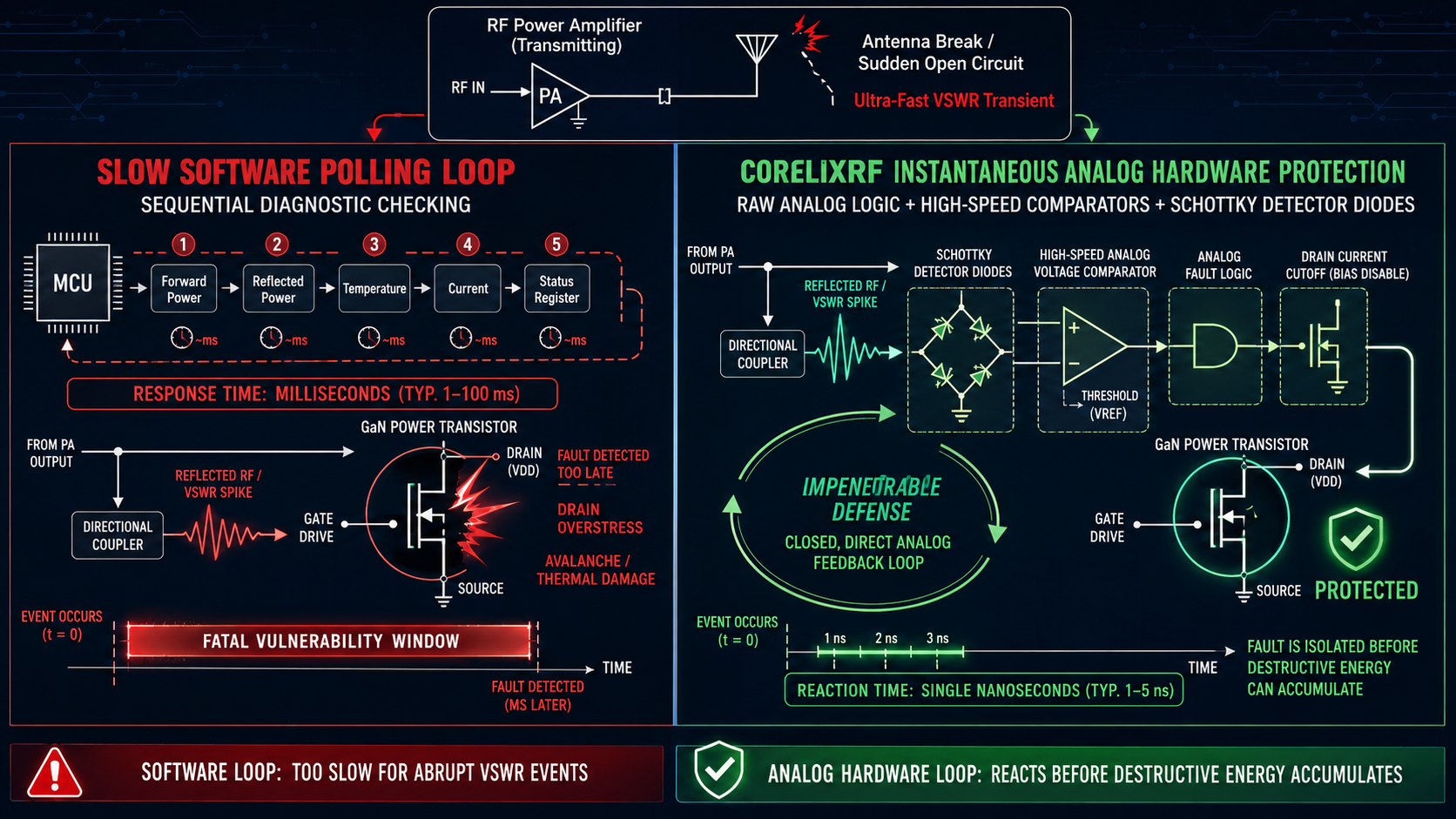
System integrators frequently face catastrophic hardware failures when high-speed data link antennas break mid-operation. Integrating lightning-fast analog hardware protection loops prevents this sudden disastrous equipment destruction completely. CorelixRF leverages two decades of rigorous field troubleshooting experience ensuring maximum survival for your critical microwave transmission setups.
1. Why Do Antennas Break During High-Speed Data Link Operations?
● Vibration mechanics
● Connector shear stress
Here is the deal, high-speed data link arrays operate under extreme mechanical stress constantly. Aviation platforms endure intense aerodynamic vibrations during high-velocity flight missions. Such kinetic forces directly impact external microwave transmission elements relentlessly. Engineers notice severe signal degradation near rigid mounting points frequently. Continuous oscillation induces insidious metal fatigue across critical coaxial junctions. Shear stress inevitably fractures delicate RF connectors over prolonged operational periods. You might be wondering, what happens next mechanically? Physical separation severs that crucial load connection instantly without warning. Total reflection occurs immediately after this mechanical break finishes. Electromagnetic energy bounces backward towards your source module rapidly. Forward power has absolutely nowhere else left for traveling. A complete open circuit replaces previously matched 50-ohm loads suddenly. Massive standing waves form aggressively along those main coaxial cables. Our field investigations reveal frequent sheared center pins within protected radomes. Standard connectors simply snap when physical alignments get catawampus under constant aerodynamic buffering forces. You must account for dynamic structural integrity limits rigorously. A compromised transmission line guarantees severe reflected energy spikes always. Case studies show unmanned aerial vehicles losing communication payloads mid-flight often. Ground stations record sudden telemetry loss during aggressive aerial maneuvers. Maintenance crews routinely discover completely detached transmitter output cables post-landing.
| Failure Mode | Primary Cause | Reflection Coefficient |
| Pin Shear | High-frequency vibration | Γ = 1 (Open Circuit) |
| Solder Crack | Thermal cycling fatigue | Γ > 0.8 (High Mismatch) |
| Thread Loosening | Inadequate torque | Intermittent Γ spikes |
2. How Does Software Polling VSWR Delay Trigger Catastrophic Failures?
● Polling loop bottlenecks
● Instantaneous mismatch mechanics
What’s the real story? Software-based monitoring loops inherently suffer from severe processing latency issues. Microcontrollers sequentially check internal voltage chassis temperature and output reflection status. This cyclical process takes several milliseconds for full diagnostic completion. Meanwhile electromagnetic waves travel near light speeds inside coaxial assemblies. Reflected energy reaches your final power amplification stage nearly instantly. Typical software cannot react fast enough during sudden open circuit events. A severed transmitting antenna generates immediate total power reflection. Truth be told, polling delays leave expensive hardware completely unprotected temporarily. Powerful transistors absorb massive reverse energy while digital processors calculate fault conditions. Those few milliseconds seem trivial for normal human sensory perception. However semiconductor internal junctions melt within microseconds under extreme standing waves. Field technicians are frequently flummoxed by burned internal components despite active software fault alarms. That embedded microcontroller simply logs an error after permanent thermal damage occurs. You cannot rely on slow digital loops for critical microwave protection. Real-time system defense demands immediate hardware-level intervention mechanisms solely. Telemetry logs often reveal temperature alerts firing milliseconds after actual power loss. Radar operators experience sudden blank screens because protective software lagged behind physics. Integrating faster processors barely mitigates this fundamental sequential polling flaw.
| Monitoring System | Average Latency | Failure Probability |
| Microcontroller Polling | 5 – 15 ms | 100% upon disconnect |
| FPGA Digital Loop | 1 – 2 ms | 85% upon disconnect |
| Pure Analog Comparator | < 50 ns | 0% (Safe) |
3. What Happens Inside RF Power Amplifiers During Sudden Mismatch?
● GaN transistor breakdown
● Thermal runaway dynamics
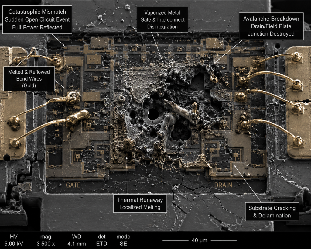
This is where it gets interesting, catastrophic mismatch alters internal impedance environments drastically. Reflected peak voltage adds constructively with forward wave amplitudes inside cavities. This superimposition creates extreme peak voltages across delicate transistor drain terminals. Gallium Nitride devices possess high electrical breakdown limits under normal operations. However a severed output load multiplies operating voltages beyond maximum safe thresholds. Dielectric breakdown ruptures those microscopic semiconductor channels almost instantly. But wait, there’s more, intense localized heating follows this sudden electrical overstress event. Extreme internal current densities vaporize microscopic metallization layers within a few microseconds. Destructive thermal runaway accelerates as internal junction temperatures spike completely uncontrollably. Engineers inspecting failed field units observe cracked ceramic device packages regularly. Melted internal gold bonding wires indicate extremely rapid catastrophic failure events. VNA S-parameter measurements show completely collapsed high-frequency gain performance curves. Network analyzers display pure short circuits at severely damaged input ports. Your communication system loses all external broadcasting capabilities immediately upon component failure. Physical substrate destruction happens long before any software mitigation algorithms intervene. Decapsulated chips under electron microscopes reveal literal cratering across active semiconductor regions. Power dissipation shifts from intended RF loads directly into fragile die structures.
| Stage | Timeframe | Physical Phenomenon | System Impact |
| 1 | < 100 ns | Voltage standing wave peak | Dielectric stress |
| 2 | 1 – 5 μs | Avalanche breakdown initiated | Irreversible junction damage |
| 3 | > 10 μs | Thermal runaway | Complete output power loss |
4. Why Cannot Standard Protection Mechanisms Prevent Instant Burnout?
● Software vs. hardware latency
● Reflected power surges
Let’s dig a little deeper, standard off-the-shelf controllers prioritize low-cost digital integration highly. They utilize shared ADC channels for monitoring multiple diagnostic parameters simultaneously. Multiplexing creates significant processing bottlenecks during critical high-speed fault events. Every single microprocessor clock cycle extends that fatal equipment vulnerability window. Reflected continuous power surges bypass these sluggish digital barriers completely effortlessly. Here is the kicker, standard commercial designs wait for multiple fault confirmations sequentially. Designers implement complex debouncing algorithms preventing annoying false positive alarms. This specific logic intentionally ignores brief transient voltage spikes during normal operation. Unfortunately a broken data link antenna creates permanent severe impedance mismatch. That intentional software delay guarantees total RF module destruction inherently. Milliseconds feel like multiple eternities for highly sensitive microwave semiconductor components. By the time mechanical relays disconnect main bias voltages your transistors are ruined. Field engineers find utterly useless error logs alongside completely incinerated amplifier circuitry. Digital fault protection provides merely a wonky sense of system security here. One case involved an aviation integrator losing three consecutive units during testing. Their legacy software loop required three consecutive failed pings before triggering shutdown.
| Protection Strategy | False Alarm Rate | Equipment Survival Rate |
| Heavy Software Debouncing | Very Low | 0% under hard fault |
| Light Software Debouncing | Moderate | 20% under hard fault |
| Hardware Direct Cutoff | Slightly Higher | 100% under hard fault |
5. How Can Oscilloscopes Detect High-Speed Data Link VSWR Latency?
● Time-domain reflection
● Triggering on power spikes
You might be wondering, how do we measure this destructive control latency accurately? Diagnostic engineers must utilize high-bandwidth oscilloscopes for accurate nanosecond transient analysis. Fast directional couplers extract forward and reverse microwave signal samples continuously. Ultra-fast detector diodes convert raw microwave energy into easily measurable baseband voltages. We configure our scope triggers specifically for sudden reverse power magnitude spikes. Truth be told, capturing this chaotic event requires extremely precise test timing setups. We intentionally sever a heavy-duty dummy load during absolute full power operation. That digital oscilloscope captures that exact microscopic moment harmful reflection initially begins. We simultaneously monitor that main amplifier gate bias control line voltage. The measured time difference between reflection onset and actual bias shutdown defines latency. Poorly designed legacy systems show dangerous loop delays frequently exceeding ten milliseconds. Modern Gallium Nitride devices fail catastrophically long before that vital shutdown command arrives. These bench level tests validate our catastrophic field failure theories absolutely perfectly. You must verify actual physical reaction times purely at nanosecond temporal scales. We recorded one commercial unit taking fifteen full milliseconds before cutting power.
| Measurement Point | Equipment Required | Expected Value | Critical Threshold |
| Reverse Power Spike | Fast Diode Detector | < 10 ns | N/A |
| Bias Shutdown Signal | Digital Oscilloscope | < 500 ns | > 1 μs (Failure) |
| Total Loop Delay | Multi-channel Scope | < 1 μs | > 5 μs (Burnout) |
6. What Constitutes True Hardware-Level VSWR Protection?
● Analog comparator limits
● Nanosecond reaction times
Now, let’s switch gears, true robust protection completely eliminates sluggish software from critical pathways. High-speed analog voltage comparators evaluate reflected signal voltages purely continuously. These dedicated analog components react within mere single nanoseconds after detecting severe faults. A fast operational amplifier scales that incoming reverse power signal appropriately for logic. Ready for the good part? This raw analog logic directly controls main gate bias switching circuits locally. Absolutely no microprocessors interpret incoming data during an emergency hardware shutdown sequence. That analog comparator cuts off primary transistor drain current immediately upon threshold breach. This direct hardware-level intervention acts significantly faster than any destructive microscopic thermal mechanisms. Your highly sensitive RF output devices survive sudden load physical disconnections completely safely. We typically implement rugged Schottky detector diodes for ultra-rapid RF signal detection. This specific analog architecture guarantees reliable component survival during catastrophic coaxial cable shears. Dedicated hardware protection provides actual physical immunity against sudden extreme impedance mismatch. Your critical aviation communication data links truly demand this precise level of rugged design. Pure analog feedback loops form an impenetrable defense against violent VSWR transients.
| Component Type | Function | Signal Processing Path |
| Schottky Diode | RF Envelope Detection | Analog Baseband |
| High-Speed Op-Amp | Voltage Scaling | Continuous Analog |
| Threshold Comparator | Fault Identification | Combinational Logic |
7. How Does CRF-PA-8G18G1500W Resolve Instantaneous Burnout Vulnerabilities?
● Built-in VSWR protection
● 8-18 GHz GaN robustness
Here is the deal, CorelixRF engineered specific robust solutions for these extremely harsh environments. Our advanced CRF-PA-8000M18000M-1500W model integrates lightning-fast analog hardware protection loops internally. This specific unit operates effectively across a broad 8,000 – 18,000 MHz frequency range. We thoughtfully designed built-in protection encompassing over-voltage over-temperature over-drive and VSWR fault conditions. What’s the real story? That internal circuit design utilizes advanced GaN technology for maximum overall durability. Our proprietary analog detection circuits bypass all slow RS485 or LAN control interfaces during emergencies. It successfully shuts down active operation microseconds before fatal transistor breakdown limits occur. Generating a rated output power reaching 1500W absolutely demands absolute failsafe operational reliability. That dedicated internal logic overrides any pending slow digital software commands instantly upon severe mismatch. Your deployed system survives abrupt external antenna breaks without sustaining any internal hardware damage. We confidently guarantee continuous safe operation through incredibly extreme external operational anomalies. High-power test scenarios prove our module withstands complete load removal at maximum output. Internal temperature sensors also act independently preventing catastrophic thermal runaway during sustained operations.
| Parameter | Specification | Purpose DOCX |
| Frequency Range | 8,000 – 18,000 MHz | Wideband data link support |
| Rated Output Power | 1500 W | Long-range transmission |
| Technology Base | Advanced GaN | High durability & efficiency |
| Internal Protection | VSWR, Over-voltage | Hardware survival guarantee |
8. Why Are 1500W Output Power And 1.5:1 VSWR Critical Specifications?
● Margin for mismatch
● Continuous wave stability
This is where it gets interesting, maintaining stable high-power operation requires immense internal design margins. The rugged CRF-PA-8000M18000M-1500W handles an input VSWR measuring 1.5:1 during normal usage seamlessly. This specific capability accommodates minor weather-related connector degradations easily before triggering annoying system alarms. Generating 1500W output power amplifies any tiny physical impedance reflection quite dramatically. You might be wondering, how exactly does active thermal cooling factor into this equation? Standard internal air cooling methods manage baseline expected thermal dissipation highly effectively. However sudden catastrophic total reflection pushes that internal thermal load far beyond normal baseline limits. Extremely robust GaN transistors withstand significantly higher operating junction temperatures momentarily without failing immediately. This specific advanced material choice provides crucial extra nanoseconds for our analog protection engagement. Our powerful internal supply requires AC 380V±10% at standard 50/60Hz frequency. Highly stable voltage feeds ensure strictly consistent analog comparator reference levels during chaotic load events. A massive nominal 62 dB gain requires strict engineering control over dangerous parasitic oscillations. These exact specific performance parameters ensure module survival under extremely severe operational stress.
| Specification | Value DOCX | Operational Benefit |
| Input VSWR Tolerance | 1.5:1 | Prevents nuisance tripping |
| Nominal Gain | 62 dB | High amplification capability |
| Operating Temperature | 0 to 50 °C | Broad environmental envelope |
9. How To Validate Protection Circuit Efficacy In Field Environments?
● Intentional mismatch testing
● Monitoring reflection transients
Let’s dig a little deeper, true field system verification demands incredibly rigorous physical testing procedures. Integration engineers install fast motorized waveguide isolation switches immediately after WRD650 output connectors. We deliberately inject a standard calibrated 0 dBm input test signal. That mechanical switch instantly toggles from perfectly matched dummy loads toward absolute pure short circuits. Truth be told, this remarkably brutal verification test destroys poorly designed inferior products almost immediately. We closely monitor that main RS485 control interface for any subsequent detailed fault reports. Our rugged amplifier must survive this violent impedance transition without any permanent performance degradation whatsoever. Subsequent diagnostic spectrum analyzer frequency sweeps confirm maintaining strict -60 dBc spurious emission levels. Recorded out-of-band harmonics remain strictly stable between -15 and -8 dBc post-recovery. We manually repeat this violent mechanical disconnection fifty separate times during initial qualification phases. Constant proven survival proves our dedicated hardware intervention acts significantly faster than catastrophic physical failure. You can completely confidently deploy these ruggedized units into extremely high-vibration aerospace platforms.
| Test Step | Action Performed | Expected Amplifier Response |
| 1 | Apply 0 dBm input | Output reaches 1500W |
| 2 | Trigger WRD650 switch | Immediate analog shutdown |
| 3 | Read RS485 status | VSWR fault logged |
| 4 | Reconnect matched load | Normal operation resumes |
10. What System Integration Practices Maximize Amplifier Longevity?
● Rigid waveguide coupling
● Active thermal management
Now, let’s switch gears, precise physical rack installation dictates long-term overall equipment reliability very heavily. You must securely tighten sensitive N-Female input connectors with appropriately calibrated torque wrenches exclusively. Prevent any harsh mechanical pulling strain across fragile RF cables during initial rack mounting procedures. Rigid heavy-duty WRD650 waveguide interfaces require perfectly clean flush mating metal surfaces absolutely. Ready for the good part? Excellent precise mechanical alignment prevents minor internal signal reflections from accumulating dangerously. Your external facility cooling infrastructure must absolutely support uninterrupted internal air flow pathways continuously. Maintain external ambient room environments strictly controlled between 0 and 50 degrees Celsius. Demanding test and measurement applications benefit greatly from proactive dampening vibration isolation mounts. Complex aviation control ground setups should utilize premium heavy-duty shock absorbers near main chassis attachments. These vital proactive mechanical precautions minimize any statistical probability regarding sudden antenna transmission line shears. Excellent thoughtful physical system integration complements our incredibly robust internal electronic protection perfectly. Together these smart engineering practices ensure maximum possible operational lifespans for critical transmission arrays.
| Integration Aspect | Recommended Practice | Failure Risk Mitigated |
| RF Input Mating | Torque wrench on N-Female | Intermittent signal loss |
| Output Interface | Flush WRD650 alignment | Standing wave accumulation |
| Ambient Control | Regulate below 50 °C | Thermal stress exhaustion |
Our rugged CRF-PA-8000M18000M-1500W solves catastrophic burnout failures through advanced GaN design alongside hardware-level VSWR protection. Stop relying on extremely sluggish software polling loops during sudden physical antenna breaks. Upgrade your fragile high-speed data link systems using true nanosecond analog intervention mechanisms today. We share your deep frustration regarding ruined expensive hardware. Contact our experienced CorelixRF engineering team immediately for detailed integration assistance.
FAQ
Q1: What is high-speed data link VSWR latency?
This term describes dangerous time delays between physical antenna breakage and actual power shutdown.
Q2: How does hardware VSWR protection work?
Extremely fast analog comparators detect reflected power spikes instantly before cutting transistor gate bias.
Q3: Why do antennas break during flight?
Constant harsh aerodynamic vibrations induce severe metal fatigue across rigid coaxial connector joints ultimately.
Q4: What control interfaces monitor fault status?
Operators access critical real-time diagnostic monitoring functions directly via RS485 or LAN interfaces.
Q5: How do engineers validate protection circuits?
Technicians utilize motorized waveguide switches deliberately causing massive intentional impedance mismatches during full operation.
VSWR protection RFQ evidence
Convert VSWR protection requirements into testable RFQ terms
For RF data links, VSWR protection should be specified as a measurable requirement: antenna/load fault condition, response time expectation, protection behavior, thermal margin, recovery logic and factory test evidence.
Frequency range, output power, gain flatness, duty cycle, waveform, load/VSWR condition and pass/fail limits.
Protection response, thermal margin, calibration chain, connector/interface limits and operating environment.
Datasheet, measured data, FAT checklist, inspection records, delivery documentation and case-style review.
CorelixRF engineering review path: for RF amplifier VSWR protection for data links, connect the article findings to a manufacturable RF chain before requesting a quote. Review RF power amplifier options, compare the UHF amplifier path when low-band coverage is involved, check custom RF front-end integration, confirm the RF antenna interface, then send band, power, duty-cycle, protection and documentation needs through engineering inquiry.