
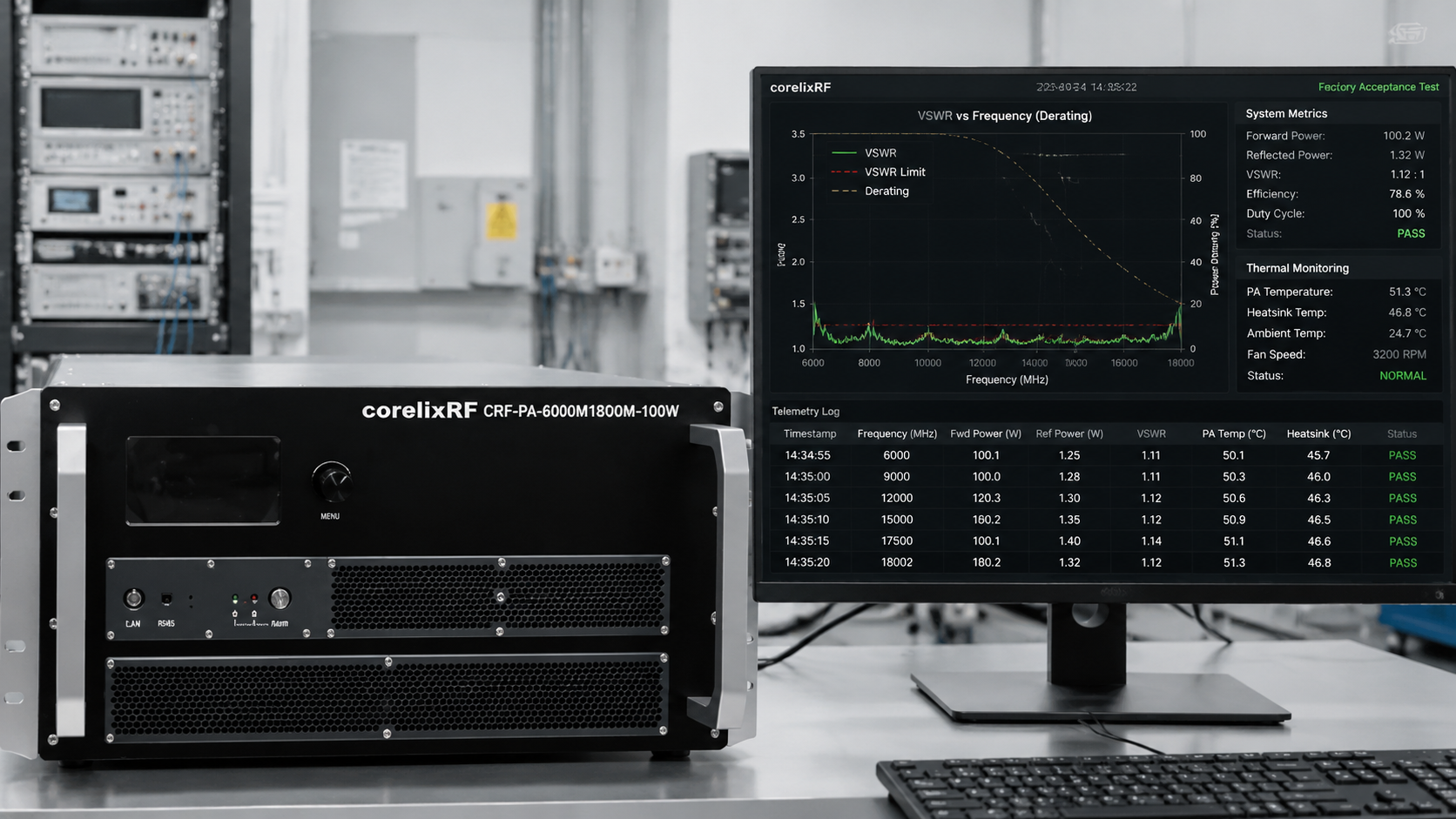
Integrators procuring radio frequency power amplifiers (RF PAs) frequently encounter a critical project failure risk: relying exclusively on standard catalog models while expecting those units to replicate datasheet peak metrics in complex, non-ideal integration environments. This idealized expectation consistently results in field strength failing to meet compliance standards during electromagnetic compatibility (EMC) chamber testing, a complete loss of continuous wave (CW) operational capacity under maximum load, and protracted after-sales disputes when hardware inevitably enters protection modes.
The objective laws of RF engineering dictate that relying solely on a “rated power” parameter from a catalog specification sheet is fundamentally insufficient for system-level execution. Standard datasheets document performance under strictly controlled, idealized laboratory conditions—typically a perfect 50-ohm termination. Real-world electronic warfare (EW) simulators, radar cross-section measurement systems, and EMC susceptibility testing environments present highly dynamic operational variables. This article deconstructs the underlying physical mechanisms responsible for these integration failures and outlines the mandatory engineering acceptance workflow required to transition from a standard testing platform to a customized, highly reliable delivery.
The Underlying Physical Mechanisms of Integration Failure
1. Impedance Mismatch and Field Strength Degradation
The primary cause of field strength failure in radiated immunity testing or EW signal transmission is impedance mismatch. The vast majority of commercial off-the-shelf RF power amplifier datasheets quantify output power using an ideal 50-ohm laboratory load, where the voltage standing wave ratio (VSWR) is practically 1.0:1. However, in physical system integration, wideband transmitting antennas exhibit significant VSWR fluctuations across their operating frequency range.
When an RF PA drives an antenna with a high VSWR, a substantial percentage of the forward RF energy is reflected back from the antenna port toward the amplifier’s final output stage, rather than being radiated into the spatial environment. This reflected power directly subtracts from the effective radiated power (ERP), causing the target zone field strength to drop rapidly below the required volts-per-meter (V/m) thresholds.
Furthermore, deploying high-power amplifiers to drive wideband antennas without strict, system-level safety logic introduces severe hardware risks. In open-loop control systems lacking precise VSWR polling and protection protocols, the sudden surge of reflected power creates high-voltage standing wave nodes along the transmission line. If the VSWR exceeds the breakdown voltage threshold of the output Gallium Nitride (GaN) High Electron Mobility Transistors (HEMTs), instantaneous catastrophic failure of the active devices or severe thermal degradation of the antenna feedlines will occur. Even before catastrophic failure, the impedance variation causes significant gain drift and severe linearity degradation, rendering the RF output unusable for precision modulation schemes.
2. Thermal Dissipation Limits and Continuous Operation Failure
A secondary, yet equally fatal, point of failure for system integrators involves thermal management during continuous wave (CW) operation. Catalog RF amplifiers often highlight peak power specifications derived from short-duration pulse testing or operation in strictly climate-controlled laboratory ambient temperatures. However, in rigorous applications such as EMC testing or sustained EW jamming, the system is required to maintain maximum CW output power for hours, or even days, continuously.
The fundamental challenge in sustained high-power RF generation is thermal dissipation. Even when utilizing highly efficient GaN solid-state power amplifier (SSPA) architectures, inefficiencies in the amplification process generate massive thermal loads. If the mechanical chassis and internal thermal resistance pathways are not strictly constrained during the engineering design phase, heat rapidly accumulates at the semiconductor junction.
As the junction temperature rises, the electron mobility within the GaN substrate decreases, leading to thermal gain roll-off and a subsequent drop in RF output power. More critically, repeated thermal cycling—transitioning from ambient to maximum operating temperature—induces severe thermo-mechanical stress. Conventional thermal interface materials, such as standard thermal grease applied between the RF pallet flange and the mechanical heat sink, are highly susceptible to the “pump-out effect.” The mismatch in the coefficient of thermal expansion (CTE) between the metal surfaces forces the thermal grease to migrate outward over hundreds of thermal cycles. This physical displacement drastically increases contact thermal resistance, trapping heat within the active device. Consequently, the amplifier triggers its thermal shutdown protection logic, completely neutralizing the system’s continuous operation capability.
3. The Diagnostic “Black Box” and After-Sales Latency
The third structural risk in adopting unverified catalog RF hardware is the lack of system-level telemetry, resulting in an after-sales diagnostic “black box.” Standard units often lack the specific remote monitoring and diagnostic interfaces required for seamless integration into Automated Test Equipment (ATE) software loops.
When an RF PA experiences an overload condition, triggers a thermal limit, or detects a critical VSWR fault in the field, it shuts down to protect itself. In a black-box configuration, the system integrator has no visibility into the specific trigger condition. Without dynamic access to internal current consumption, stage-by-stage temperature logs, or real-time forward and reverse power metrics, system engineers cannot isolate the fault. What should be a routine software adjustment or a minor antenna tuning exercise escalates into a mandatory, weeks-long return and repair process, requiring the hardware to be shipped back to the factory for physical teardown. This latency severely impacts the system’s Mean Time To Repair (MTTR) and jeopardizes the overall project delivery schedule.
The Correct Acceptance Standard: From Standard Platform to Deep Customization
The engineering methodology required to mitigate these risks necessitates a paradigm shift: abandoning direct catalog procurement in favor of executing a customized engineering review based on a standard, verified platform.
Consider the wideband RF power amplifier platform CRF-PA-6000M18000M-100W. As a foundational technical platform operating across a multi-octave 6 GHz to 18 GHz frequency range and delivering 100 W of nominal output power, its core GaN RF chain and 4U rack-mount mechanical architecture are rigorously proven. However, when deployed into a specific system integration project, this standard unit must serve merely as a baseline for the following mandatory customization and acceptance verifications:
1. Real-World Load Capacity and Derating Verification: The procurement acceptance criteria must immediately pivot from the theoretical “output power at 50 ohms” to the quantified “available forward power under the customer’s specific VSWR curve.” Integrators must provide the measured return loss of their specific antenna system across the entire frequency band. The RF manufacturing factory must then compute and provide an accurate power derating curve, validating exactly how much forward power can be reliably sustained at the worst-case impedance mismatch frequencies without triggering protective shutdown.
2. Microsecond VSWR Polling and Safety Isolation Logic: To ensure equipment survivability, the RF system’s internal control logic must be custom-configured to enforce strict safety boundaries between the high-power RF source and the system load. The underlying VSWR polling latency within the CRF-PA-6000M18000M-100W control board must be quantified and customized to operate in the microsecond domain. This guarantees that if a severe antenna mismatch occurs—such as a disconnected RF cable or a damaged radiating element—the amplifier detects the reflected power spike and executes an over-drive protection cutoff instantly, isolating the hardware before thermal or voltage breakdown occurs.
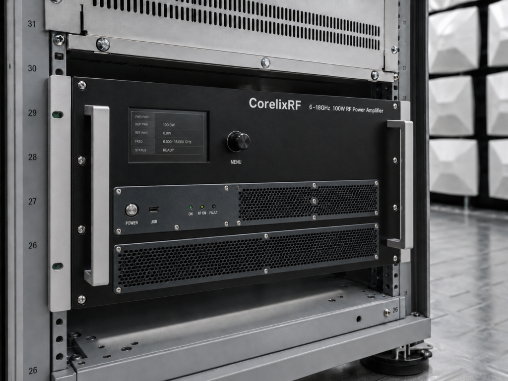
3. Diagnostic Protocol Customization and Telemetry Access: To eliminate the after-sales diagnostic latency, the standard RF platform must be upgraded to include project-specific telemetry interfaces. Integrators must mandate the inclusion of RS485 or LAN interfaces running standardized protocols. The factory must open the internal telemetry registers, allowing the integrator’s host control system to dynamically pull forward/reverse power readings, cascaded module temperatures, and real-time current draw. This transparency enables the integrator to implement predictive maintenance, dynamically adjust signal generator drive levels based on real-time gain data, and isolate system faults instantaneously without relying on factory teardowns.
CorelixRF’s Delivery Standard: System Integration Driven by Empirical Evidence
With a 30-year operational history in microwave and RF manufacturing, CorelixRF maintains a strict operational mandate: empirical laboratory data is the sole valid metric for hardware delivery. We recognize that system integrators do not require opaque RF enclosures; they require highly transparent, precisely quantified engineering components.
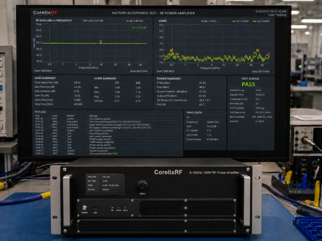
For any customized project derived from our standard RF platforms, such as the CRF-PA-6000M18000M-100W, our Factory Acceptance Test (FAT) extends far beyond theoretical datasheet extrapolations. We deliver comprehensive, objective evidence. This includes actual gain flatness plots measured across the entire multi-octave band, continuous CW burn-in logs captured at the specified maximum ambient operating temperatures, and verified thermal imaging reports documenting heat dissipation under active load. Every manufactured unit is subjected to rigorous thermal design validation to conclusively eliminate the risk of performance drift caused by interface material degradation, ensuring stable, long-cycle continuous wave output.
The success of a high-stakes system integration project must never be predicated on the idealized parameters of a standard catalog brochure. Implementing a rigorous RF hardware evaluation during the initial project phase is the fundamental prerequisite for achieving field strength compliance and guaranteeing long-term system reliability.
Submit your project’s target frequency band, measured antenna VSWR curves, CW or pulse waveform parameters, and physical mechanical constraints. Align directly with the CorelixRF engineering team within 48 hours to establish a customized hardware selection, derating calculation, and FAT validation plan based strictly on the empirical realities of your system environment.
Use the standard platform as the engineering baseline
A standard platform works best when the customization delta is explicit: frequency window, output level, connector type, control interface, enclosure, cooling and test documentation. This makes lead time and risk easier to control.
Recommended next step: send the operating band, required output power, duty cycle, load condition, control interface, cooling limit, protection behavior and required FAT documents. CorelixRF can map this customizing standard RF amplifiers requirement to a standard platform, a controlled modification or a custom RF build.