
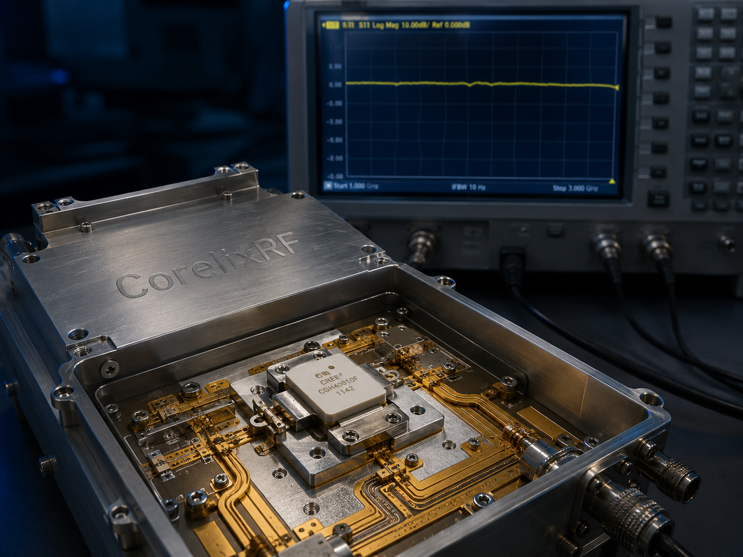
In the procurement and system integration of radio frequency architectures, the most expensive trial-and-error cost stems from a common misconception: the assumption that the “nominal rated power” on a supplier’s datasheet will directly translate to the target field strength in a live operational environment. For engineering teams constructing continuous-wave (CW) communication platforms or EMC laboratories operating above the 1 GHz band, relying solely on baseline marketing specifications is a direct path to catastrophic project delays.
When a standard commercial RF amplifier is integrated into a complex test bench, the physical realities of the laboratory rapidly expose the gap between theoretical parameters and manufacturing reality. Wideband antennas do not present perfect loads. High-frequency coaxial cables introduce significant insertion loss and phase shifts. Furthermore, continuous operational cycles demand that the equipment outputs at its physical limits without interruption. Under these conditions, “datasheet power” frequently collapses, resulting in inadequate field strength and thermal runaway. Compounding this issue for system integrators is the fact that most amplifiers operate as a “black box”—providing zero warning before a critical hardware failure occurs.
This article deconstructs the underlying physical mechanisms that cause RF amplifiers to fail in the field. Utilizing the empirical data and hardware architecture of CorelixRF, we establish a rigorous engineering standard for procurement acceptance, ensuring continuous, uncompromising performance upon delivery.
The Physics of Failure: Why Nominal Power Does Not Equal Target Field Strength
To understand why RF amplifiers fail during critical test cycles, we must examine the physical and thermodynamic realities of the 1,000 MHz to 6,000 MHz wideband RF signal path. The degradation of field strength is never a random anomaly; it is the inevitable outcome of impedance mismatches and thermal engineering blind spots.
Impedance Mismatch and the High-Frequency VSWR Reality
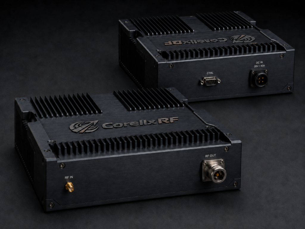
In a theoretical model, a power amplifier drives a flawless 50 Ω load. However, in an actual anechoic chamber, wideband antennas spanning 1 GHz to 6 GHz exhibit drastic variations in return loss across different frequency points. This creates an immediate physical impedance mismatch.
When the load deviates from 50Ω, the Voltage Standing Wave Ratio (VSWR) rises sharply. This means a substantial percentage of the RF energy—which should have been converted into radiated field strength—is reflected back into the amplifier’s final-stage output transistors. If the amplifier operates as a black box, the system integrator remains blind to this severe mismatch. The reflected power dissipates as massive localized heat, leading to an immediate drop in forward gain and, ultimately, the dielectric breakdown of core active components.
Gain Drift and Thermal Blind Spots in Continuous Operation
Many commercial RF amplifiers boast a “200W” rating based solely on low-duty-cycle pulsed testing. Yet, in actual CW immunity testing, the equipment must operate near its 1dB compression point (P1dB) for hours.
If the thermal resistance from the transistor junction to the baseplate is inadequate, and the external control system cannot monitor internal temperatures in real-time, semiconductor carrier mobility will plummet as temperatures spike. This triggers severe gain drift. An amplifier outputting nominal power at minute one will inevitably experience power collapse as it reaches thermal saturation, completely invalidating the test cycle.
CorelixRF Empirical Evidence: Breaking the Black Box with Engineering Truth
At CorelixRF, we recognize that our clients are building mission-critical infrastructure with zero margin for error. We do not deliver ambiguous specifications; we deliver industrial-grade hardware backed by hardware-level monitoring capabilities and laboratory-verified empirical data.
Hardware-Level Link Transparency: Pin-Accurate VSWR and Thermal Monitoring
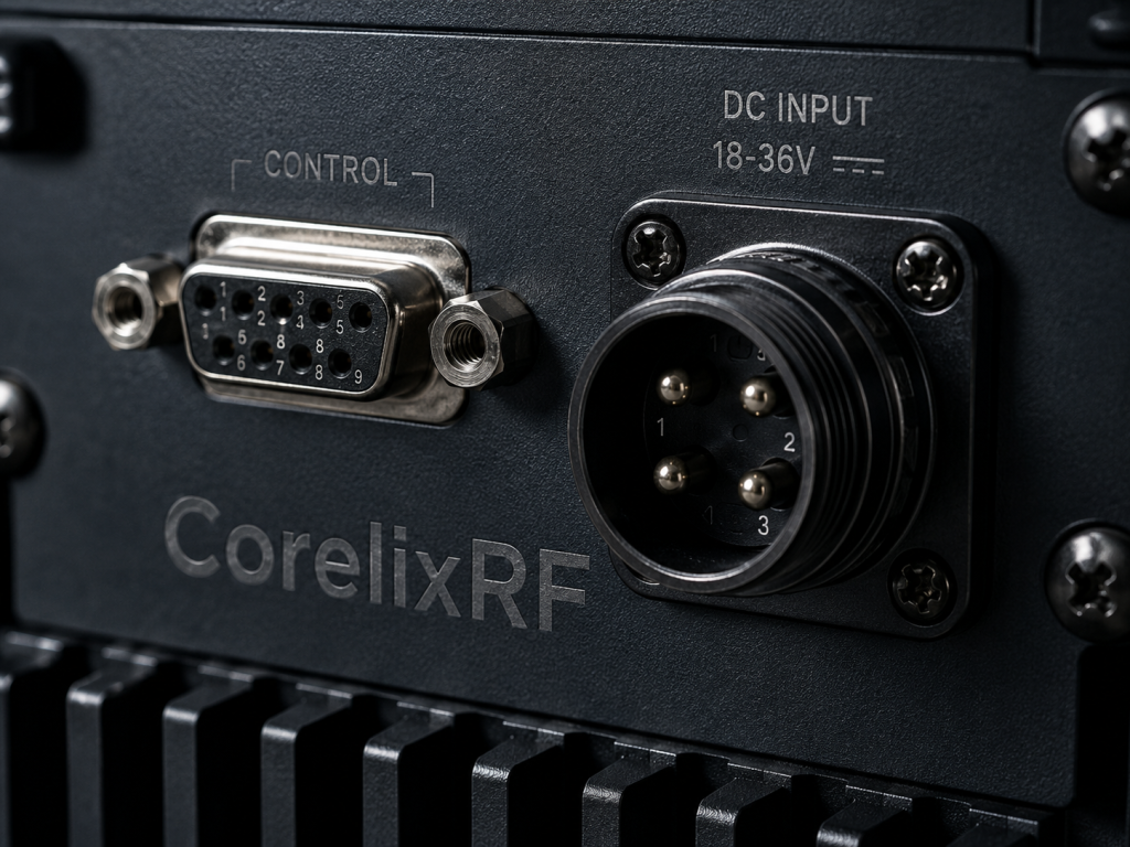
To eliminate the integrator’s fear of “black box” failures, CorelixRF engineered a system-level monitoring architecture into the core of our designs. Take the CRF-PA-1000M6000M-200W wideband solid-state power amplifier as the prime example. While it delivers 53 dB of gain and 200W of rated power across the 1,000-6,000 MHz band, its true engineering value lies in its DB9 control interface.
Rather than relying on rigid internal trip-thresholds, we convert critical physical metrics into detectable voltage outputs for your overarching test system:
- Real-Time VSWR Monitoring: Through Pin 6 (Forward Power Monitor) and Pin 7 (Reverse Power Monitor) on the DB9 interface, the master control system can read the exact VSWR status of the RF link with millisecond precision. If antenna switching or cable degradation causes a mismatch, your system detects the physical anomaly before hardware damage occurs.
- Thermal Runaway Prevention: Pin 8 (Temperature Monitor) provides real-time internal temperature voltage feedback. Paired with our robust 28V DC air-cooling architecture, integrators can accurately evaluate thermal redundancy during full-load CW operation, eliminating the risk of test-ruining gain drift.
- Precision Gain Control: Via Pin 4 (Attenuation Adjustment, 0-3.0V DC Input), the host computer can execute smooth, analog attenuation control over the output link without power interruption, perfectly accommodating the strict field strength stepping requirements of complex test standards.
Continuous Wave Factory Acceptance Testing (FAT)
Beyond transparent hardware interfaces, every amplifier module shipped from CorelixRF undergoes punishing mismatch survivability and thermodynamic validation.
For the CRF-PA-1000M6000M-200W, our strict FAT protocol dictates prolonged full-load burn-in into high-power dummy loads at the absolute boundary of its 2:1 maximum input VSWR tolerance. Our delivery logs include wideband swept frequency curves, precise gain flatness data (strictly maintained within ±5 dB), and verified output records meeting -10 dBc harmonic suppression standards. This quantitative data proves that, from structural thermodynamics to PCB trace routing, the equipment will maintain rock-solid field strength from the first minute of testing to the last.
Secure Your System Reliability Today
Purchasing an RF power amplifier based on optimistic nominal specifications is a gamble that inevitably leads to thermal failure and costly project delays. True system reliability is rooted in transparent hardware monitoring architectures, rigorous physical verification, and comprehensive FAT documentation.
CorelixRF provides the pin-level control interfaces and empirical evidence required to ensure your test systems operate flawlessly under the most extreme conditions.
Schedule a 48-Hour Engineering Review with CorelixRF Today.
Do not let unverified RF links compromise your next system integration. Contact our senior engineering team with your specific frequency bands, target field strength, and system control protocols (such as RS485 integration). We will provide a precise engineering breakdown and hardware selection within 48 hours.
Turn this RF requirement into a quotable specification
Use this article as a starting point for a buildable RF specification. Before quoting, CorelixRF normally checks frequency range, output power, gain flatness, duty cycle, load mismatch, thermal path, control interface, enclosure limits and acceptance data.
- RFQ checklist – send the data buyers usually forget, including band, power, duty cycle, interface and test standard
- delivery documentation – check what documents can support incoming inspection, FAT review and long-term maintenance
- quality and certification review – review the quality and compliance evidence before the project moves into procurement
- testing documentation – define curves, burn-in evidence and acceptance records before shipment
- case studies – review similar engineering paths before sending an RFQ
- RF configurator – turn frequency, power, thermal and interface requirements into a first configuration brief
- engineering contact – send the application notes, block diagram or target specification to engineering sales
For a faster review, send operating band, power target, modulation or waveform, antenna/load condition, cooling limit, mechanical envelope and target test standard through the RFQ or contact path.