
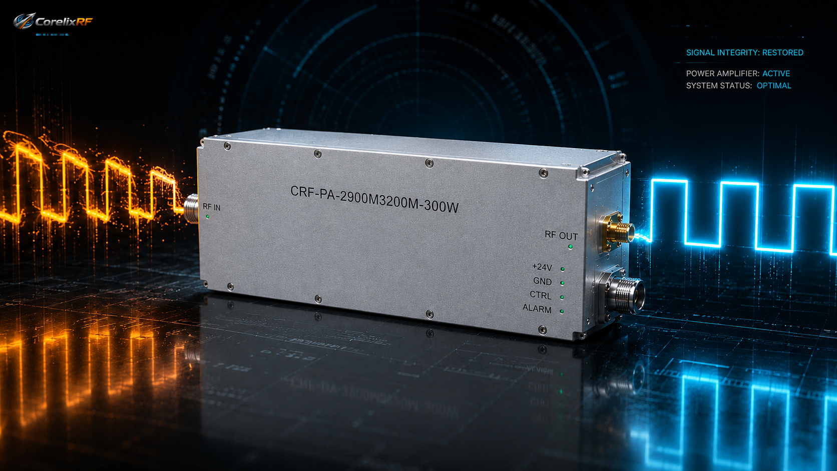
During the R&D and integration of radar detection RF front-ends or Electronic Warfare (EW) jamming systems, project teams often encounter a frustrating phenomenon: the RF Power Amplifier (RF PA) perfectly meets the peak power requirements during static testing, but once integrated into the real system and subjected to modulated signals with specific Pulse Repetition Frequencies (PRF), the radar’s range resolution deteriorates sharply, or the target suppression probability of the jamming system drops significantly.
The root cause of such system-level failures often lies in R&D engineers mistakenly applying the evaluation logic of Continuous Wave (CW) amplifiers to the selection of pulsed amplifiers. By fixating solely on the static parameter of “rated peak power,” they completely overlook the dynamic distortions of the pulse envelope in the time domain—specifically, the irreversible impacts caused by Pulse Droop, edge timing (Rise/Fall Time) distortion, and transient thermal responses.
For rigorous RF engineering, the quality of the pulsed signal directly determines the success or failure of the system. This article deeply analyzes the underlying physical mechanisms of pulse envelope distortion and provides you with engineering selection and acceptance criteria backed by laboratory data.
The Underlying Physical Mechanisms and System Disasters of Pulse Droop
Under long Pulse Width (PW) operation, pulse droop is an unavoidable physical phenomenon. When the amplifier is in the pulse “On” state, its transient current demand is immense, causing the power supply and the module’s internal decoupling capacitors to begin discharging.
- Energy Depletion and Gain Attenuation: If the internal power modulation network is poorly designed or the decoupling capacitor capacity is insufficient, the drain voltage will experience a significant drop toward the end of relatively long pulse widths, such as 15 us. This voltage drop directly causes a decrease in the transistor’s output power, manifesting as a downward tilt (droop) at the top of the pulse in the time-domain waveform.
- Fatal Flaw for Radar and Modulation: In modern pulsed Doppler radars or complex pulse-modulated communications, Digital Signal Processing (DSP) algorithms demand exceptionally high flatness of the echo envelope. A pulse droop of 2 dB or even 3 dB means the effective transmitted energy at the end of the pulse is slashed by half. This not only severely degrades the Signal-to-Noise Ratio (SNR) of long-range targets but also introduces additional phase distortion (AM-PM effect), leading to the broadening of the matched filter output and directly destroying the radar’s range resolution and velocity measurement accuracy.
- The Engineering Truth: An excellent pulsed power amplifier must utilize precise power distribution network design to control the droop within an extremely narrow margin under specified pulse widths, ensuring a uniform output of RF energy throughout the entire pulse cycle.
Pulse Edge Distortion: How Rise/Fall Time Destroys Timing Control
The rise time and fall time of a pulse are primarily limited by the slew rate of the amplifier’s bias switching circuit and the group delay of the RF chain.
- Pulse Energy Truncation: For narrow pulse applications of 1 us or even shorter, if the rise time is sluggish (e.g., exceeding 500 ns), the amplifier fails to reach saturated output power for a large portion of the pulse cycle. This causes the actual radiated effective RF energy to be drastically lower than the theoretical calculation.
- Timing Dead Zones and Noise Interference: A sluggish fall time (trailing effect) is equally fatal. In radar systems, the receiver must immediately enter the “Listen” mode after the transmitter shuts off. If the PA’s RF output cannot cleanly and rapidly turn off (achieving sufficient isolation), residual RF energy will leak into the receiving front-end, saturating the receiver’s Low Noise Amplifier (LNA) and creating a severe system “blind spot.”
Transient Thermal Response: The “Invisible Killer” at High Duty Cycles
Unlike the steady-state thermal accumulation of CW amplifiers, pulsed amplifiers face extremely intense transient thermal shocks. At high duty cycles of up to 20% or 25%, the junction temperature (Tj) of a GaN transistor surges within the microsecond duration of the pulse “On” time and briefly cools during the pulse interval.
- Thermal Stress Fatigue: Such high-frequency, severe thermal cycling generates massive mechanical and thermal stress on the underlying bonding wires and die attach layers of the chip.
- Inter-Pulse Gain Drift: If the thermal resistance of the module’s baseplate is too high, heat cannot dissipate during the pulse intervals, causing the base temperature to escalate progressively. This reduces carrier mobility, triggering not only macroscopic output power degradation (thermal derating) but also a complete collapse of amplitude and phase consistency between continuous pulse trains.
CorelixRF Engineering Empirical Evidence: The CRF-PA-2900M3200M-300W Case
To eliminate the integration risks posed by time-domain distortion, strict pulse time-domain acceptance specifications must be established. At CorelixRF, we reject ambiguous catalog parameters and only provide real laboratory data based on extreme pulsed conditions.
Take the CRF-PA-2900M3200M-300W (GaN Pulsed Solid-State Power Amplifier), specifically developed for test instrumentation and radar communication systems, as an example. This product outputs 300 W peak power in the 2.9 GHz to 3.2 GHz band, and its underlying design completely resolves the challenge of pulse waveform fidelity:
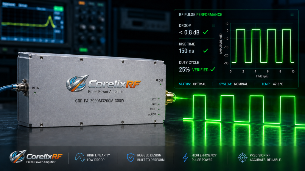
- Rigorous Time-Domain Waveform Control: Under test conditions of 1-15 us pulse widths and up to 25% duty cycles, the module’s typical pulse droop is strictly controlled to within 1 dB. Simultaneously, the measured rise/fall times are ≤200 ns, ensuring the squareness of the RF pulse envelope and perfectly meeting the stringent envelope flatness requirements of radar signal processing.
- Dedicated High-Speed Control Logic: Designed for complex system-level timing integration, this product is equipped with dedicated RS485-3.3V interface logic. The system’s main controller can achieve microsecond-level high-speed Enable control, completely avoiding the RF trailing issues caused by slow-responding analog switches.
- System-Level Survivability: In addition to withstanding the transient thermal shocks of high-density pulse modulation, we have integrated over-voltage, over-temperature, over-drive, and Voltage Standing Wave Ratio (VSWR) protection and alarm circuits. Even if a severe impedance mismatch occurs at the antenna end, the amplifier can execute a nanosecond-level hardware protective shutdown before the reflected pulse energy destroys the core transistors.
Stop Ineffective Integration, Establish Engineering Boundaries
Do not let vague pulse parameters delay your R&D progress. Before integrating a pulsed power amplifier into your system, you must demand that your supplier provides oscilloscope-detected waveform screenshots, droop readings, and long-term thermal imaging evaluation records under specific pulse widths and duty cycles.
If you are architecting the front-end for a pulsed radar, RF jamming system, or SDR link, and require strict control over pulse timing, droop, and thermal design, please contact the senior engineering team at CorelixRF directly.
[Submit an RFQ / Book a 48-Hour Engineering Review]
Please include your target operating frequency band, pulse width range, duty cycle, control interface timing requirements, and VSWR tolerance expectations. A CorelixRF senior RF application engineer will deliver an engineering matching assessment, backed by empirical lab evidence, within 48 hours.
Pulsed radar amplifier RFQ review
Translate pulsed radar amplifier requirements into measurable RFQ fields
Pulsed RF amplifier procurement should define pulse width, duty cycle, rise/fall behavior, droop, peak/average power, blanking or protection logic, cooling and factory test records before supplier selection.
Pulse width, duty cycle, peak/average power, rise/fall time, droop, blanking and synchronization needs.
Band coverage, gain flatness, thermal limits, load/VSWR condition, protection logic and control interface.
Measured data, FAT checklist, inspection records, delivery documentation and engineering review before shipment.
Radar RF amplifier RFQ checklist
For RF amplifier for radar systems searches, define whether the requirement is for authorized laboratory testing, radar component evaluation, pulse-chain validation or RF front-end integration. Do not compare suppliers using only headline power; pulse behavior and acceptance evidence matter.
- Define frequency range, pulse width, duty cycle, rise/fall time and droop.
- Specify rated output power, load condition, VSWR behavior and thermal environment.
- Ask for FAT data, waveform screenshots, protection test notes and delivery documentation.
- Compare pulsed RF amplifier platforms, solid state power amplifiers, RFQ checklist and engineering contact.
CorelixRF engineering review path: for pulsed RF power amplifier selection, connect the article findings to a manufacturable RF chain before requesting a quote. Review RF power amplifier options, compare the UHF amplifier path when low-band coverage is involved, check custom RF front-end integration, confirm the RF antenna interface, then send band, power, duty-cycle, protection and documentation needs through engineering inquiry.