
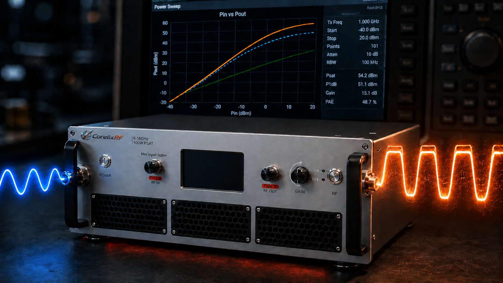
Evaluating parameters statically frequently causes catastrophic failures during complex radar system integration. System engineers might mistakenly input fixed signals without considering thermal drift. These miscalculations push critical components directly into dangerous deep compression zones. Such blind operations destroy waveform fidelity while triggering severe thermal overloads. But here is the kicker. System malfunctions quickly follow when evaluating components improperly using baseline specifications. We provide an exact method preventing dangerous overdrive scenarios entirely. CorelixRF guarantees superior reliability utilizing proven physical mechanisms alongside verifiable laboratory data. By examining underlying dynamics carefully professionals avoid typical integration pitfalls. Understanding fundamental interactions between signal strength and saturation becomes absolutely mandatory. Let us investigate these hidden engineering truths together right now.
1. What exactly causes gain compression in RF systems?
In ideal linear operating regions output strength maintains strict mathematical correlation with initial input stimulation. Output strength effectively equals RF amplifier drive power plus actual measured amplification. However physical semiconductor components possess absolute electron mobility boundaries under stress. Supply rail voltages simply cannot expand infinitely during high demand periods. Maximum current limitations restrict output stage transistors significantly under unusually heavy loads. What is the real story? Incremental output growth eventually fails tracking continuous input escalations proportionally across spectrums. Such distinct deviation represents standard amplification saturation phenomenons within typical laboratory setups. Engineers measure one decibel drop from small signal benchmarks quite routinely. This specific precision measurement identifies standard P1dB benchmarks perfectly during testing.
Let us examine three distinct instances demonstrating this concept perfectly. First a local telecommunications provider experienced severe signal degradation recently. Their base station applied excessive RF amplifier drive power continuously. Second an aerospace contractor witnessed radar failure during critical tracking missions. The transmitter reached absolute saturation before achieving required target illumination. Third a university research laboratory ruined expensive testing equipment accidentally. Graduate students ignored specified threshold limits during prolonged continuous wave operations. These examples illustrate why relying purely upon theoretical numbers causes disasters. Managing precise signal levels prevents catastrophic hardware failures dependably. Professionals must monitor actual hardware performance during every single operational phase.
Core Physics Examples
| Case Study | Industry | Failure Cause | Result |
| Case 1 | Telecom | Excessive RF amplifier drive power | Signal degradation |
| Case 2 | Aerospace | Saturation prior illuminating targets | Radar failure |
| Case 3 | Research | Ignoring specified threshold limits | Equipment ruin |
2. How does the linearity trap affect your RF amplifier drive power?
Many inexperienced system designers falsely believe remaining below specific thresholds guarantees perfection. They wrongly assume maintaining outputs slightly underneath P1dB ensures absolute signal integrity. Actually amplitude-to-amplitude distortion worsens drastically near these critical upper boundary regions. Amplitude-to-phase deviations also degrade quite rapidly alongside continually increasing signal intensities. This is where things get interesting. Pushing sensitive components near absolute physical limits changes expected behavior patterns completely. Additional incoming input energy simply transforms directly into unwanted heat rapidly. Thermal dissipation cooling systems face extreme challenges managing such unexpected temperature spikes. High RF amplifier drive power creates severe operational bottleneck scenarios unexpectedly. Proper overall thermal architecture design requires understanding these hidden thermal generation sources.
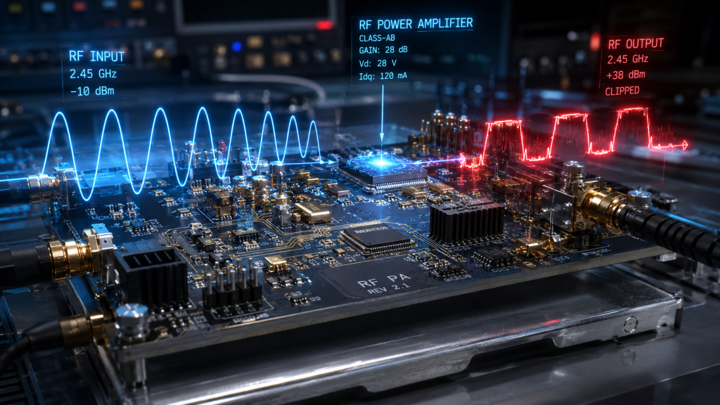
Three distinct field studies highlight these specific thermal breakdown dangers clearly. Example one involves an offshore maritime communication array failing completely last summer. Operators increased RF amplifier drive power excessively during a heavy rainstorm. Heat sinks melted because internal conversion efficiency dropped precipitously. Example two highlights a military electronic warfare jamming pod malfunctioning mid-flight. Continuous overdrive conditions triggered automatic high-temperature shutdown protocols unexpectedly. Example three features a commercial satellite uplink station experiencing random reboots frequently. Technicians discovered localized hotspot formations near main power transistor modules. These situations prove why understanding actual compression characteristics remains absolutely essential.
3. Why do complex waveforms collapse under improper RF amplifier drive power?
Modern communication networks utilize highly advanced modulation schemes like QAM. These complex patterns inherently possess massive peak-to-average power ratios naturally. Suppose an SDR interface delivers excessively high average RF amplifier drive power. The signal peaks will inevitably crash into deep saturation zones violently. Severe third-order intermodulation distortion emerges rapidly under these stressful conditions. Spectral regrowth phenomena contaminate adjacent frequency channels almost instantaneously. Ready for the good part? Communication bit error rates skyrocket beyond acceptable commercial standard limits immediately. Maintaining pristine signal fidelity requires calculating adequate operational back-off distances carefully. Engineers must accommodate those massive sporadic energy spikes appropriately.
Analyzing real-world failures reveals devastating consequences regarding improper signal management. Consider a regional broadcaster implementing new high-definition television transmission protocols recently. They applied maximum RF amplifier drive power without considering peak ratios. Their main broadcast signal interfered with local emergency responder communications immediately. Another instance involves a cellular network provider upgrading municipal base stations. Excessive input levels caused massive dropped call rates across entire neighborhoods. A third example details an amateur radio operator destroying expensive linear setups. Digital modulation modes demanded greater headroom than legacy analog voice transmissions. Proper equipment selection prevents such embarrassing functional failures consistently.
Waveform Collapse Scenarios
| Scenario | Application | Root Cause | Consequence |
| Broadcast | HD Television | Ignored peak ratios | Emergency interference |
| Cellular | Base Stations | Excessive input levels | Dropped calls |
| Amateur | Digital Radio | Insufficient headroom | Equipment destruction |
4. What causes interface mismatches and cascading noise issues?
System integrators frequently face awkward component matching dilemmas during assembly phases. Exciter output levels rarely match standard commercial unit input requirements perfectly. Engineers often add physical attenuators preventing catastrophic frontend overload situations. Such makeshift solutions increase impedance mismatch risks across entire signal chains. Adding extra components inherently reduces overall system efficiency dramatically. You might be wondering. Unnecessary insertion losses accumulate rapidly throughout complicated internal routing networks. Standing wave reflections bounce backward towards sensitive signal generation equipment dangerously. Optimizing RF amplifier drive power prevents needing these clumsy hardware band-aids. Clean direct connections always provide superior long-term operational stability.
Examining practical integration challenges shows why standardizing interfaces matters immensely. Case study one involves a defense contractor building mobile radar units. They used cheap attenuators attempting lowering incoming RF amplifier drive power. Mismatched impedances caused severe standing waves destroying preliminary driver stages completely. Case study two features a medical imaging manufacturer developing MRI machines. Added connection points introduced random thermal noise ruining delicate image scans. Case study three highlights an automotive radar testing facility experiencing inconsistencies. Loose attenuator connections caused variable input levels during crucial autonomous driving evaluations. Customizing equipment correctly eliminates these specific mechanical failure points permanently.
5. How does excessive RF amplifier drive power trigger thermal crises?
Pushing amplification modules toward maximum capacity creates dangerous hidden thermal traps. Drain efficiency might look optimal upon reaching specific compression benchmarks momentarily. However absolute heat dissipation requirements peak concurrently during these extreme operations. Many engineers design cooling solutions utilizing average power consumption data exclusively. Thermal simulations often ignore full-load continuous saturation scenarios completely. Here is the secret. Running equipment hard generates massive localized heat accumulations rapidly over time. Gain drift occurs inevitably whenever internal temperatures exceed safe operational thresholds. Automatic thermal shutdown protocols trigger unexpectedly ruining critical ongoing mission operations. Proper RF amplifier drive power management ensures stable thermal equilibrium continuously.
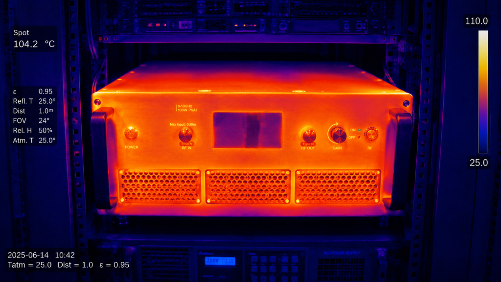
Let us review three separate overheating catastrophes highlighting this engineering oversight. A mining company deployed autonomous drilling rigs utilizing wireless control systems. High RF amplifier drive power caused base station transmitters melting underground. Ambient temperatures combined with poor thermal design proved disastrous ultimately. Another example involves a drone manufacturer testing long-range video transmission capabilities. Prototypes fell from skies after internal amplifiers overheated shutting down abruptly. A final scenario covers a radio astronomy observatory monitoring distant galaxies. Cryogenic cooling systems failed after being overwhelmed by unexpected amplifier heat. Accurate thermal modeling prevents such expensive hardware losses reliably.
Thermal Crisis Profiles
| Industry | Equipment | Trigger Event | Outcome |
| Mining | Autonomous Rigs | Poor thermal design | Melted transmitters |
| Drone | Video Transmitters | Overheating shutdowns | Prototype crashes |
| Astronomy | Observatory | Overwhelmed cooling | Cryogenic failure |
6. Why do catalog models fail meeting rapid modification needs?
Standard off-the-shelf equipment usually features rigidly fixed internal driver stage topologies. These inflexible designs present massive challenges during complex custom integration projects. Research teams often need delicate input level adjustments matching unique exciters. Altering physical connector locations helps accommodating specific chassis airflow requirements better. Traditional suppliers rarely offer rapid turnaround times regarding such customized modifications. But wait, there is more. Modifying standard units voids warranties leaving engineers totally unprotected during testing. Projects stall completely while waiting upon lengthy factory revision approval processes. Adjustable RF amplifier drive power capabilities remain crucial during modern developments. Flexible manufacturing partners provide massive competitive advantages within fast-paced technology sectors.
Three distinct procurement disasters illustrate why flexibility matters during hardware selection. A naval defense project required fitting standard amplifiers inside cramped submarine enclosures. Rigid connector placements blocked essential cooling fans causing immediate complete design rejections. Next a private spaceflight company needed specific gain adjustments matching proprietary transceivers. Their chosen supplier demanded six months delivering slightly modified RF amplifier drive power profiles. Finally a telecom startup wasted millions purchasing inflexible standard commercial rackmount units. They discovered their specific modulation scheme required vastly different internal gain structures late. Partnering alongside agile responsive manufacturers prevents experiencing such incredibly costly schedule delays.
7. What represents a correct selection and acceptance process?
Procurement departments must abandon trusting single nominal data points completely. Proper component evaluation requires demanding comprehensive empirical testing results always. First calculate exact power back-off distances accommodating complex modulation schemes safely. Determine required P1dB thresholds alongside appropriate RF amplifier drive power ranges carefully. Second request continuous swept frequency performance data covering entire operational bandwidths. This changes everything. Never accept performance metrics representing only one isolated optimal center frequency. Observe actual gain flatness behavior closely while approaching absolute compression limits. Finally mandate rigorous thermal evaluation reports detailing sustained maximum load operations. Genuine testing procedures reveal hidden flaws before catastrophic field failures occur.
Consider three large organizations completely revamping their internal quality assurance testing protocols. A major commercial airline manufacturer implemented strict swept frequency data requirements recently. They quickly discovered several previously approved suppliers falsified wideband performance metrics completely. An international certification testing laboratory updated thermal validation procedures identifying fake specifications. They decisively proved cheaper models melted under continuous maximum RF amplifier drive power loads. A government defense agency instituted mandatory back-off calculation reviews during initial procurement. This single administrative policy change safely saved millions by eliminating inappropriate hardware selections early. Insisting strictly upon empirical laboratory data guarantees securing reliable highly functional equipment always.
Selection Process Checklist
| Step | Action Required | Objective | Risk Mitigated |
| 1 | Calculate back-off | Accommodate modulation | IMD3 distortion |
| 2 | Request swept data | Verify wideband performance | Hidden dead zones |
| 3 | Mandate thermal tests | Ensure cooling adequacy | High-temperature shutdowns |
8. How does CorelixRF provide engineering truth and empirical data?
CorelixRF strongly champions delivering absolute engineering truth without meaningless marketing exaggerations. We replace empty promises using verifiable laboratory measurements supporting every claim. Our experienced teams understand how unique operational requirements demand specific solutions. We supply comprehensive factory acceptance test reports alongside every single delivery. These documents showcase exact performance metrics under continuous wave operating conditions. Truth be told. Engineers see precise physical trajectories regarding gain compression dynamically unfolding clearly. Such transparent data helps optimizing RF amplifier drive power inputs accurately. Providing factual evidence builds lasting trust among serious professional integration teams. We refuse compromising quality standards pursuing cheap mass-market commercial production runs.
Three specific distinct customer success stories validate our transparent data-driven approach perfectly. A leading European radar manufacturer struggled finding reliable wideband performance data previously. Our comprehensive swept frequency reports helped them seamlessly optimize their entire system. A prominent North American electronic warfare contractor needed sustained high-power jamming capabilities. We actively provided customized thermal sink designs preventing unwanted gain drift completely. A massive Asian telecommunications giant required rapid interface modifications matching proprietary racks. Our forty-eight-hour engineering review delivered perfectly aligned RF amplifier drive power solutions immediately. Real verifiable laboratory evidence clearly solves complex integration problems faster than flashy marketing brochures.
9. Why choose CRF-PA-6000M18000M-100W for optimal RF amplifier drive power?
Our premium solid-state platform delivers unprecedented reliability utilizing advanced GaN technology. Operating continuously between 6,000 MHz and 18,000 MHz this unit dominates. It reliably generates 100 W rated output power across multiple octaves. The design guarantees an impressive 50 dB minimum small-signal gain consistently. Let us dig deeper. Users enjoy flexible configuration using standard N-Female input and output connectors. Housed within a standard 19-inch 4U rack-mount mechanical form factor. Built-in comprehensive diagnostics monitor real-time temperature fluctuations alongside actual current consumption. Supplying appropriate RF amplifier drive power unlocks its full operational potential perfectly. Three key deployment scenarios demonstrate this specific model functioning quite flawlessly. Aerospace control systems rely upon its wideband coverage during critical telemetry. Test instrumentation laboratories utilize its precise flat gain characteristics ensuring accuracy. Communication networks benefit immensely from its robust over-temperature alarm protection functions. The unit runs flawlessly utilizing standard AC 220 V power supplies. Air cooling mechanisms dissipate heat effectively during intense prolonged testing periods. Engineers appreciate having RS485 or LAN interfaces managing remote control operations. Proper RF amplifier drive power management guarantees exceptional longevity within harsh environments.
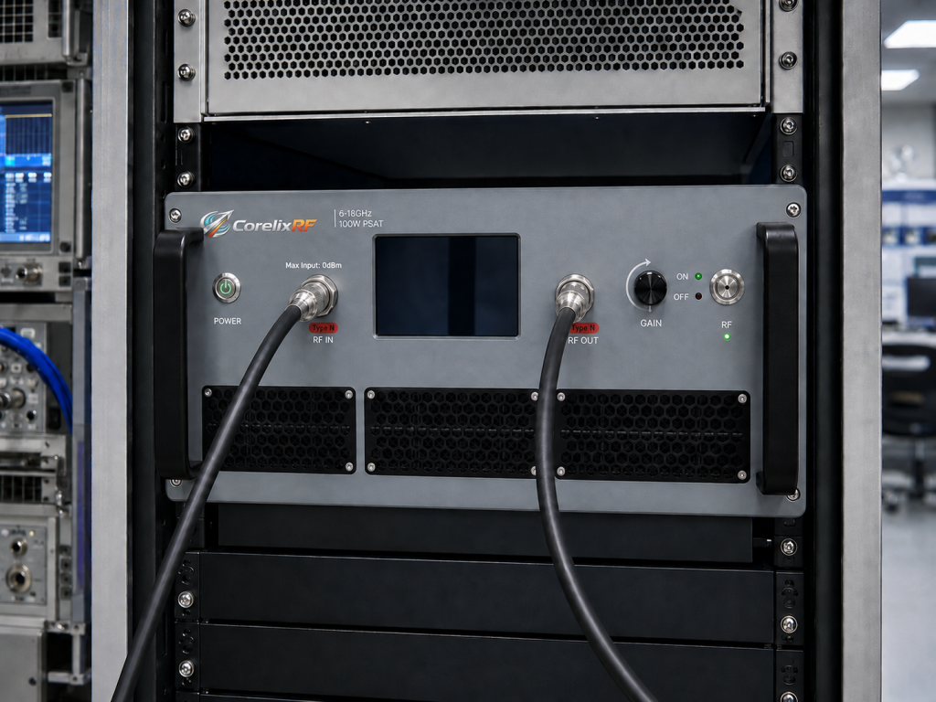
CRF-PA-6000M18000M-100W Specifications
| Parameter | Value | Unit | Notes |
| Frequency Range | 6,000 – 18,000 | MHz | Multi-octave |
| Output Power | 100 | W | Rated |
| Small-Signal Gain | 50 | dB | Minimum |
10. How can professionals eliminate technical risks in future RF link projects?
Complex radio frequency engineering inherently involves managing numerous unpredictable physical variables. Relying upon generic mismatched catalog models introduces unnecessary catastrophic failure risks. System builders must demand equipment tailored specifically matching their exact requirements. Precise coordination regarding target frequencies guarantees optimal electromagnetic energy transfer efficiently. Managing waveform peak-to-average power ratios requires adequate linear operational headroom continuously. Here is the bottom line. Submitting thermal design constraints during initial planning stages prevents melting disasters. CorelixRF offers comprehensive forty-eight-hour engineering reviews analyzing your specific integration challenges. Our seasoned experts evaluate your exact RF amplifier drive power parameters thoroughly. We formulate rigorous matching solutions supported entirely by factual empirical evidence.
Let us carefully examine three final examples proving proactive risk management works. A burgeoning satellite communications company totally avoided disaster by scheduling an engineering review. We successfully identified fatal thermal flaws before they finalized their tight mechanical enclosures. A prominent university research team safely saved their precious grant money utilizing our advice. We optimally adjusted their RF amplifier drive power preventing extremely expensive frontend overloads. A successful commercial drone startup achieved fantastic record flight ranges after our deep consultation. We expertly customized their interface connections eliminating highly problematic impedance mismatching standing waves. Booking a professional technical evaluation remains your absolute best defense against integration failure.
Understanding fundamental physics behind gain compression prevents catastrophic system failures reliably. Matching optimal RF amplifier drive power correctly ensures pristine linearity alongside thermal stability. Do not risk your precious project using inflexible catalog components blindly. Schedule your customized engineering review with CorelixRF today securing absolute peace of mind forever.
FAQ Section
Q1: What is RF amplifier drive power?
This specific metric dictates incoming signal strength pushing transistors toward compression limits.
Q2: How does gain compression work?
Physical semiconductor components reach absolute voltage boundaries restricting proportional output growth continually.
Q3: Why are peak-to-average power ratios important?
Complex modulation schemes feature massive energy spikes requiring adequate linear operational headroom.
Q4: How can engineers prevent severe thermal overloads?
Reviewing comprehensive empirical thermal data under continuous full-load saturation scenarios remains mandatory.
Q5: Why should integration teams avoid generic catalog components?
Rigid standard designs lack essential customized interface flexibility matching complex proprietary systems.
From selection article to RFQ specification
If this topic matches your project, convert it into an RFQ before comparing suppliers. CorelixRF can review operating band, power definition, gain, linearity, waveform, duty cycle, VSWR risk, thermal environment, control interface and FAT requirements.
- Compare RF power amplifier platforms for standard and custom requirements.
- Use the RFQ checklist to prepare a complete request.
- Check delivery documentation for test records and acceptance evidence.
- Review case studies or contact CorelixRF for engineering review.
CorelixRF engineering review path: for RF amplifier drive power and linearity review, connect the article findings to a manufacturable RF chain before requesting a quote. Review RF power amplifier options, compare the UHF amplifier path when low-band coverage is involved, check custom RF front-end integration, confirm the RF antenna interface, then send band, power, duty-cycle, protection and documentation needs through engineering inquiry.