
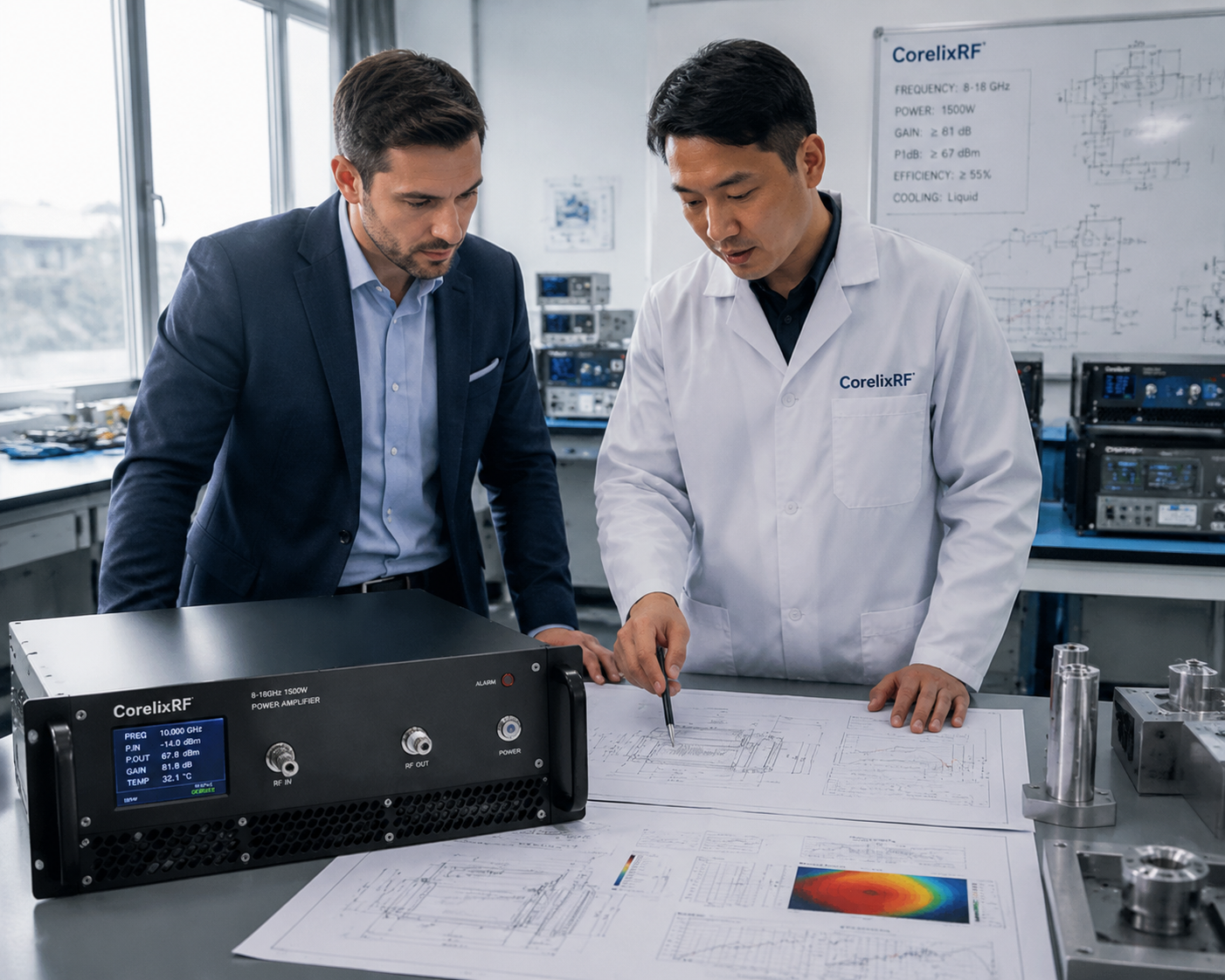
Why do we ask about application scenarios before quoting, rather than directly offering the lowest price? High-power RF system procurement managers frequently encounter severe hardware damage due to thermal runaway or poor impedance matching during the final integration and acceptance phases. Unqualified RF hardware suppliers often only provide baseline specifications on paper that lack long-term laboratory validation, inducing buyers to make blind procurement decisions based on cheap initial quotes. Days later, extremely demanding full-load testing will expose severe linearity degradation of high-power solid-state power amplifiers in actual field environments. The procurement team will have to face catastrophic project schedule delays, with hundreds of man-hours and exorbitant budget costs vanishing instantly. But the fact remains accurate B2B technical quotes must be based on comprehensive baseline application scenario data. CorelixRF insists on providing objective factory-measured specifications, combined with deep physical operational mechanism analysis to help assess system risks. Purchasing high-power, high-frequency hardware requires both the buyer and the manufacturer to firmly uphold objective engineering truths. Before providing a formal commercial quote, we always insist that the buyer provide detailed underlying boundary operating parameters. This rigorous factory review process can effectively prevent the risk of hardware meltdown caused by impedance mismatch during Factory Acceptance Testing (FAT) later on, thereby sparing the buyer’s engineering integration team from extremely tedious troubleshooting and buck-passing.
1. What Causes High-Power RF System Acceptance Failures?
Disconnect Between Paper Technical Specifications and Actual Physical Characteristics in the Laboratory
Many RF integration systems crash during the final acceptance phase because unscrupulous suppliers deliberately conceal the actual thermal performance limits of solid-state amplifiers under extreme temperatures in their technical agreements. Low-cost amplifier components operating under continuous wave (CW) full-load conditions inevitably suffer from severe gain drift within their internal transistors. Some suppliers may prominently label a rated output power of 1500 W on their datasheets; however, during actual field deployment or joint testing, minor changes at the antenna end can cause severe impedance mismatch. High levels of reverse reflected power will rapidly travel down the transmission line, completely destroying the expensive internal GaN power transistors in a very short time. Procurement professionals must bear the heavy cost of system downtime and project delays for these engineering flaws hidden behind low prices. During this period, tedious warranty claim processes often take months, while the final delivery deadline for system integration relentlessly slips away. What is the real situation? Poorly defined boundary application scenarios directly cause RF hardware to exhibit extreme fragility when facing complex modulated waveforms. Radar simulation and electronic warfare system-level testing require RF power amplifiers to have absolute baseline power output stability and excellent linearity. A simple price tag devoid of specific application context often conceals the underlying physical mechanisms that determine an amplifier’s survival rate. Our thirty years of experience in high-power microwave manufacturing show that manufacturers who blindly offer low quotes often only deliver inferior hardware that fails to meet industrial continuous operation standards. Before calculating accurate hardware production costs, we absolutely require buyers to clarify the specific operating waveforms of their target systems.
Analysis of Acceptance Failure Risk Factors
| Risk Factor | Potential Physical Mechanism | Specific Impact on the Project |
| False Technical Specs | Internal amplifier thermal runaway | Causes severe project schedule delays |
| Severe Gain Drift | Output signal severely distorted | Complete failure in system integration acceptance |
| Thermal Design Flaws | Internal RF components melt down | Results in long-term system downtime and paralysis |
2. How Does VSWR Affect the Amplifier’s True Output Power?
Thermodynamic Destruction Mechanisms Behind High Reverse Energy
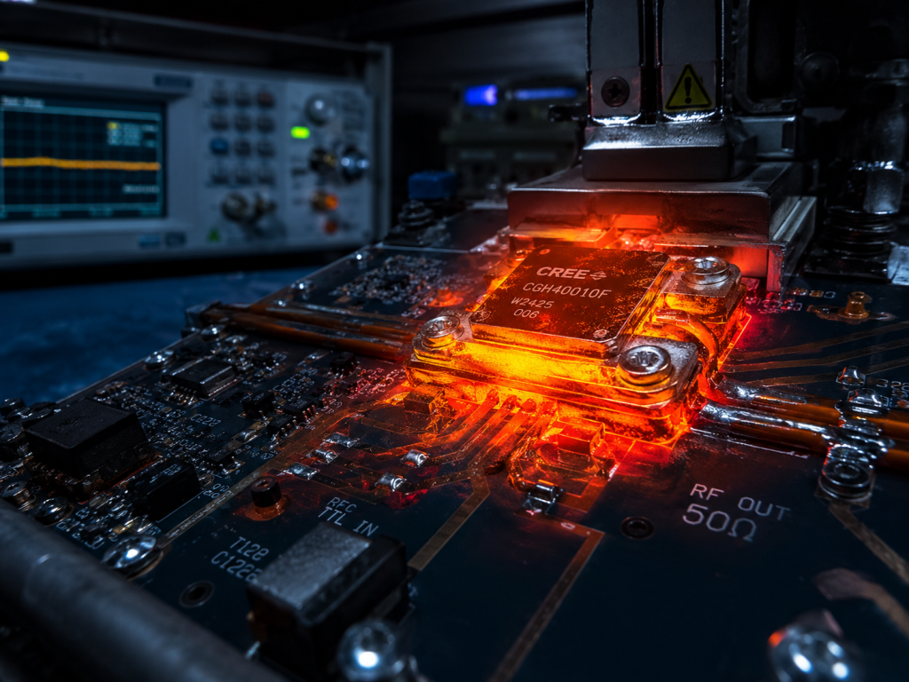
Rigorous system-level test results show that the actual output capability and service life of an amplifier are completely governed by underlying RF physical laws. The Voltage Standing Wave Ratio (VSWR) directly determines the safety margin of high-frequency power transistors during operation. When impedance is mismatched, the unradiated reverse high-frequency energy transforms into massive internal thermal stress, causing the transistor junction temperature to rise sharply. The CRF-PA-8000M18000M-1500W solid-state power amplifier developed by CorelixRF can stably provide a typical input VSWR of 1.5:1 across the ultra-wideband frequency range of 8 GHz to 18 GHz. This excellent physical parameter fundamentally ensures the amplifier’s baseline stability when facing different RF source inputs. You might be wondering how do changes in ambient temperature worsen these underlying parameters through chain reactions? Under long-term continuous full-power output, the rise in the amplifier’s internal junction temperature forces the entire power supply system’s current to experience abnormal spikes. To keep material costs down, cheap assembled amplifiers often omit built-in overdrive protection and overvoltage alarm circuits. Once the field test environment deteriorates, systems lacking hardware-level safety nets expose fatal technical blind spots, causing hundreds of thousands of dollars worth of microwave backbone hardware to be instantly scrapped. Long-term laboratory test data proves that continuous high VSWR mismatch not only reduces useful output power but also causes the amplifier’s linearity metrics to degrade exponentially.
Chain Physical Effects of VSWR Mismatch
| Detection Metric | Potential Physical Consequence | Recommended Prevention and Protection Measures |
| Excessive Reflected Power | Physical degradation of power transistors | Deploy built-in real-time VSWR alarm systems |
| Drastic Thermal Stress Changes | RF output signal distortion | Introduce rigorous data-driven temperature tracking |
| Abnormal Current Spikes | Power supply modules endure overload pressure | Integrate high-precision real-time current monitoring modules |
3. Why Must Standard Industrial Quotes Be Broken Down in Detail?
How Customized Control Interfaces and Complex Mechanical Forms Reshape Costs
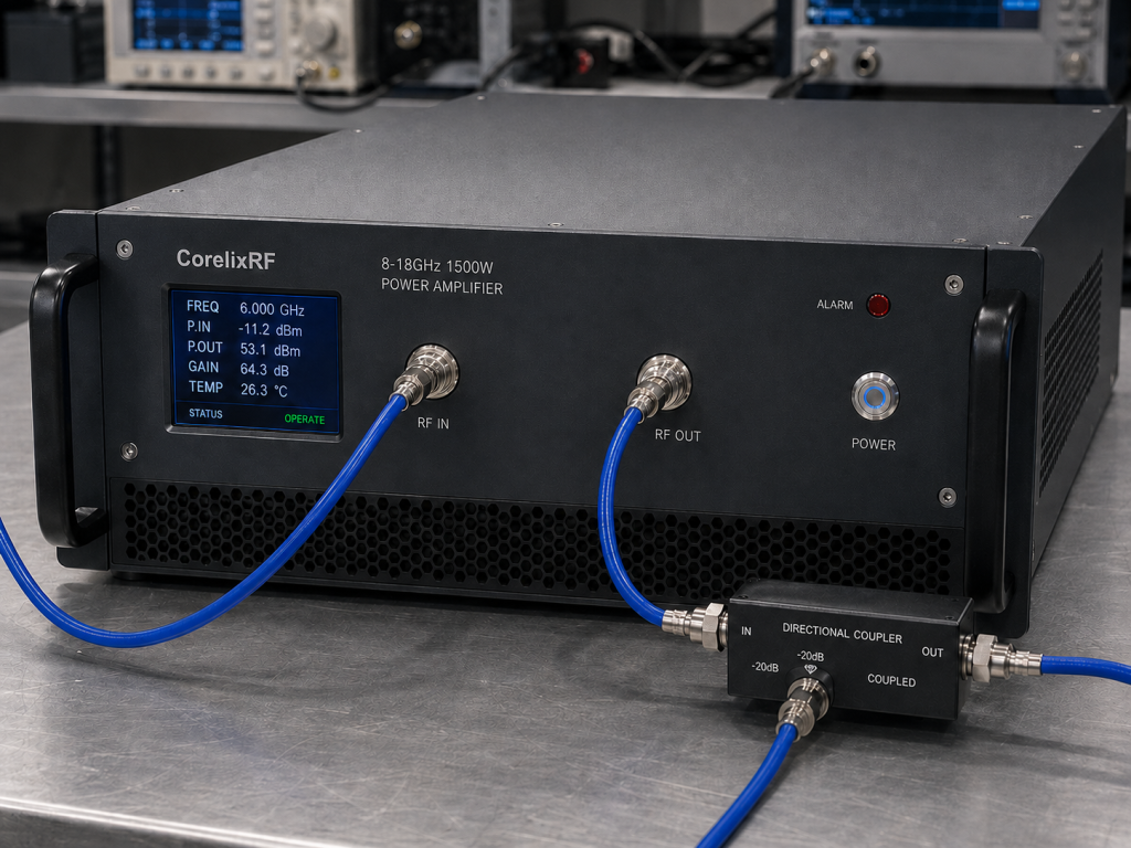
In professional microwave engineering procurement, the base price of a barebone module can never equate to the final total cost of full system integration. For an industrial-grade RF power amplifier system capable of long-term stable operation, its cost structure is heavily dictated by its mechanical form and thermal management mechanisms. The massive heat generated by high-power operation places extremely stringent requirements on the geometric topology of the air-cooling heat dissipation within the chassis, which means high-volume fans, precise air duct designs, and special machining processes will directly reflect in the bill of materials. This is the essence of the issue A complete professional B2B quote necessarily includes the cost of control protocol customization and hardware interface matching for specific projects. To ensure the CRF-PA-8000M18000M-1500W smoothly integrates into the buyer’s existing bus system, our factory needs to configure standard RS485 or LAN remote monitoring communication interfaces. Providing high-precision N-Female input terminals and WRD650 ultra-wideband waveguide output structures capable of handling kilowatt-level microwave energy requires extremely high-precision machining using 5-axis CNC machines. Clients in the aerospace and defense testing sectors typically also require us to provide dedicated 3D mechanical drawings for virtual installation reviews prior to production. Generic standard production test configurations can rarely adapt directly to variable field application environments. We will never provide irresponsible estimated figures before ascertaining the buyer’s bus control logic, mechanical interface constraints, and environmental heat dissipation conditions.
Detailed Classification of RF Hardware Costs
| Hardware Form Category | Technical and Specification Description | Corresponding Project Integration Requirement |
| Control & Communication System | Integrated RS485 or remote LAN | Matches the host computer’s communication protocol |
| Thermal Management Hardware | High-volume industrial air-cooling structure | Meets environmental sealing and cooling needs |
| Physical Interface Components | Employs WRD650 high-power waveguide | Ensures lossless transmission of high-power RF energy |
4. How Do Rigorous Engineering Reviews Fundamentally Prevent Project Delivery Disasters?
Building a Full-Process Quality Trust Chain Relying on Objective Measurement Metrics
Implementing multi-dimensional upfront technical reviews is an unshakable foundational procurement methodology for our factory. CorelixRF refuses to participate in any form of vicious low-price competition, as high-quality microwave power amplifiers are the product of combining precise physical laws with strict manufacturing processes. We make it mandatory to conduct comprehensive and rigorous mathematical model calculations on the target frequency range, rated output power, and input power dynamic range provided by the buyer. Ready to understand the engineering details? During the technical review phase, our engineering team proactively provides buyers with complete initial mechanical drawings and historical empirical test data packages under standard production configurations. This front-loaded process is designed to assist the buyer’s technical team in conducting scientific technical reviews early in the project, thoroughly eliminating the hidden technical gaps that may exist between paper datasheets and physical equipment. Stably providing 1500 W of full-band solid-state RF output power requires the amplifier to possess a minimum small-signal gain of 62 dB, and its internal gain flatness must be strictly controlled within the specified plus or minus decibels. By conducting multiple rounds of technical alignment before signing the commercial contract, we can accurately assess the actual thermal load under continuous wave or pulsed operation states, thereby completely eliminating field burnout incidents caused by insufficient thermal design margins.
Standard Laboratory Verification Technical Metrics
| Basic Technical Metric | Strict Factory Testing Standard | Final System Verification Target |
| Small-Signal Gain | Guaranteed no less than 62 dB across full band | Ensures communication links have high dynamic range |
| Rated Output Power | 1500 W full-load operational inspection | Meets field RF signal coverage requirements |
| Gain Control Range | Supports 20 dB continuous adjustable attenuation | Provides extremely high operational flexibility at high frequencies |
5. What Essential Procedures Are Included in Standard RF Hardware Acceptance Verification Steps?
Establishing Quantified Test Configurations in Advance to Eliminate Post-Delivery Disputes
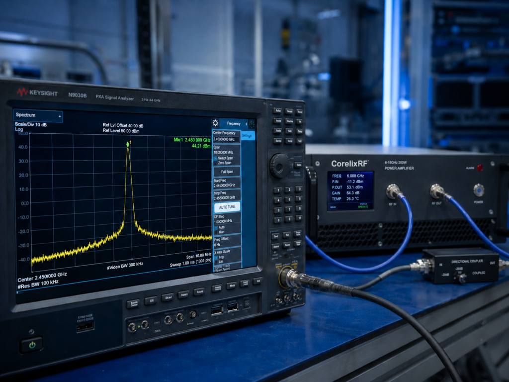
Throughout the delivery lifecycle of kilowatt-class high-power RF hardware, establishing a standardized and repeatable Factory Acceptance Testing (FAT) and Site Acceptance Testing (SAT) process is the key to ensuring successful project completion. The calibration status of testing and measurement instruments, the insertion loss of transmission cables, and the load endurance capacity must all be accurately aligned under specific application scenarios. We insist on conducting comprehensive extreme boundary assessments on amplifiers in a controlled 50-ohm standard system environment, using rated 3-phase 380V AC input power. Let’s look at the facts Our factory manufacturing process is entirely placed under the strict monitoring of the ISO 9001 quality management system, and every solid-state power amplifier shipped generates a dedicated digital quality record. We provide project-based compliance regulatory documents and complete empirical harmonic curve charts to buyers; these detailed documents can help procurement managers quickly pass expert panel reviews during site acceptance testing. By rigorously testing the amplifier’s second and third harmonic indicators to ensure typical values are better than -15 dBc, we can effectively prevent catastrophic electromagnetic interference from high-order harmonics to adjacent sensitive channels. Simultaneously, controlling the noise floor below -20 dBm/MHz and suppressing spurious emissions below -60 dBc can guarantee that the amplifier provides extremely clean spectral output in complex electronic warfare or communication backgrounds.
Factory Outbound Acceptance Inspection Metrics
| RF Physical Characteristic Inspection Area | Stringent Metric Control Target | Final Test Verdict |
| High-Order Harmonic Suppression Capability | Typical values must be better than -15 dBc | Only packed and shipped if judged fully qualified |
| System Noise Floor Level | Maximum limited to -20 dBm/MHz | Only packed and shipped if judged fully qualified |
| Spurious Signal Suppression Capability | Must be below -60 dBc across the full band | Only packed and shipped if judged fully qualified |
6. Why Do Different Operating Waveforms Fundamentally Change the Hardware’s Physical Architecture?
Differentiated Thermal Stress of CW and Pulse Modulated Signals on GaN Transistor Pins
Many procurement personnel lacking a microwave background often mistakenly assume that as long as the maximum output power is the same, the internal hardware structure of amplifiers is entirely universal. However, the time-domain characteristics of RF waveforms generate fundamentally different physical stresses on internal GaN power transistors. Continuous wave (CW) signals require the amplifier to continuously output massive amounts of RF energy to external loads every single second, posing extreme challenges to the entire unit’s heat dissipation capability and the power module’s continuous current supply. The truth of the matter is even with the same 1500 W rated output power, if the application scenario involves radar pulse modulated signals, the physical buffer provided by the duty cycle allows the instantaneous high heat generated by the transistors to conduct outward through the heat sink baseplate during the pulse intervals. However, if a low-cost amplifier designed specifically for pulsed operation is blindly thrown into a continuous wave operating scenario, the internal power components will experience catastrophic thermal runaway meltdown within seconds due to localized heat accumulation. The reason we tirelessly confirm the buyer’s system operating waveform, pulse width, and maximum duty cycle during the quotation stage is precisely to conduct comprehensive customized engineering designs from the ground up—from underlying transistor selection and matching network capacitor voltage ratings to the thickness of the cooling aluminum fins.
7. How Should Modern B2B Procurement Teams Scientifically Build a Supplier Trust System?
Replacing Aggressive Low-Price Business Negotiations with Detailed Objective Data Loops
Against the backdrop of increasingly complex global high-tech supply chains, noble business trust cannot be built on verbal promises or aggressive low prices lacking data support. Before making large-capital decisions, modern B2B procurement managers and RF system integrators must learn to request complete physical empirical evidence chains from suppliers. Factories with genuine source manufacturing capabilities are never afraid to articulate complex physical boundary conditions; instead, they will proactively assist clients in sorting out detailed technical questionnaires. Ultimately a supplier who repeatedly confirms environmental constraints, power supply fluctuations, control interfaces, and modulation characteristics before quoting is the true engineering partner dedicated to protecting your project’s successful operation. We refuse to provide cheap baseline quotes devoid of physical backing because every high-power solid-state amplifier must stably demonstrate excellent gain control linearity and ultra-low spurious performance over a wide operating temperature range of 0 to +50 °C. By providing transparent engineering truths during the early commercial alignment phase, CorelixRF helps global buyer teams effectively avoid exorbitant rework sunk costs caused by mechanical interference, software protocol incompatibilities, or insufficient heat dissipation capabilities later on.
Excellent procurement of RF systems requires not only focusing on budget rationality but also making it mandatory for suppliers to provide rigorous physical measurement metrics and full-inspection test reports. Deeply verifying boundary application scenarios before quoting can fully ensure that the solid-state amplifier hardware delivered to your laboratory forms a perfect physical loop with the actual field operating environment. CorelixRF always upholds objective engineering truths and never blindly recommends cheap, incompatible hardware with hidden technical risks for short-term commercial gain. You are welcome to contact our application engineering team today immediately to download and use the standardized Factory Acceptance Testing (FAT) and Site Acceptance Testing (SAT) execution specification templates for free, using technical data strictly validated by the laboratory to safeguard your high-power integration projects.
Q1: What is a Factory Acceptance Test?
A Factory Acceptance Test is a full-inspection assessment process conducted on various physical measurement indicators in a controlled laboratory environment at the manufacturing factory, according to the technical agreement, before the RF amplifier is packed and shipped.
Q2: What specific physical damage does impedance mismatch inflict on high-power solid-state amplifiers?
Impedance mismatch prevents RF energy from radiating efficiently to the external load; a massive amount of reverse reflected power converts into intense internal thermal stress, causing the GaN power transistor junction temperature to exceed limits and resulting in thermal meltdown.
Q3: Why must manufacturers of solid-state power amplifiers request detailed operating duty cycle data before design? The operating duty cycle directly dictates the time ratio of heating to cooling for the amplifier’s transistors; manufacturers need this time-domain waveform data to accurately calculate the heat dissipation area and airflow ratio of the thermal management system.
Q4: Compared to traditional traveling-wave tube amplifiers, what are the significant operational advantages of GaN-based solid-state amplifiers? Solid-state power amplifiers based on GaN technology possess extremely high baseline stability, wider instantaneous operating bandwidths, native support for complex diagnostic protections, and zero risk of high-voltage breakdown.
Q5: How should procurement teams effectively identify low-price technical traps when facing a myriad of microwave amplifier solutions on the market? Procurement teams should mandate that suppliers provide historical full-inspection empirical data curves, detailed 3D mechanical drawings including interface definitions alongside their commercial bids, and critically review whether they possess integrated hardware-software real-time protection circuits.
Procurement and FAT review
Prevent FAT failures by defining acceptance evidence before purchase
FAT failures often start during procurement. Buyers should define the real application, test setup, duty cycle, antenna/load condition, acceptance data and delivery records before selecting an RF amplifier supplier.
Frequency range, output power, gain flatness, duty cycle, waveform, load/VSWR condition and pass/fail limits.
Protection response, thermal margin, calibration chain, connector/interface limits and operating environment.
Datasheet, measured data, FAT checklist, inspection records, delivery documentation and case-style review.
CorelixRF engineering review path: when this article applies to RF amplifier procurement, FAT risk control and specification review, connect the technical findings to a manufacturable RF chain before procurement. Review RF power amplifier options, RFQ checklist, testing documentation, engineering inquiry so frequency band, output power, duty cycle, protection, interfaces and acceptance documents are aligned before the quote request.