
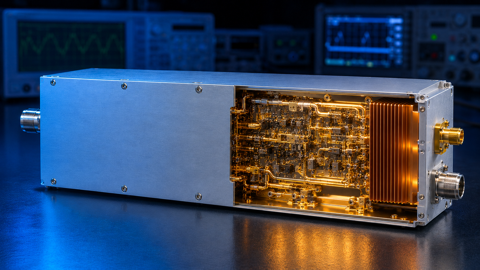
System integrators frequently face a critical decision during RF power amplifier (RF PA) procurement: select a standard catalog model or invest time and budget into full customization? To compress R&D cycles, engineers often ask suppliers to “tweak” standard platforms—requesting a 20% output power boost within the original chassis or converting a pulsed mode directly into continuous wave (CW) operation.
However, RF engineering contains no shortcuts around the laws of physics. Such assumptions regarding standard models often trigger system-level failures during final integration: thermal runaway under continuous operation, failure to achieve target radiated Field Strength, or persistent Voltage Standing Wave Ratio (VSWR) alarms under complex antenna loads. These failures ultimately launch prolonged, expensive Return Merchandise Authorization (RMA) battles.
To guarantee delivery reliability, this article defines the physical boundaries of RF amplifier modification utilizing CorelixRF’s laboratory test data and engineering practices. We clarify which modules permit rapid adaptation from standard platforms and which parameter shifts absolutely mandate a fundamental redesign.
Why “Tweaking” Triggers System-Level Failures
In Electronic Warfare (EW), radar, or high-intensity EMC testing systems, the RF amplifier is never an isolated black box. It is the most power-intensive and impedance-mismatch-sensitive nonlinear component in the entire signal chain.
Customer pain points consistently center on three metrics: Field Strength compliance, continuous operation capabilities, and after-sales stability. If integrators attempt to force higher output power without overhauling the thermal management architecture, the junction temperature (Tj) of the power transistors (e.g., GaN HEMTs) spikes violently. Physics dictates that every 10°C rise in junction temperature halves the device’s Mean Time Between Failures (MTBF), accompanied by severe gain drift and linearity degradation. This guarantees continuous operation test failures, distorts the output signal spectrum, and ultimately prevents the effective field strength at the antenna from reaching compliance.
The Green Zone: Boundaries for Rapid Standard Platform Modification
When project lead times are severely constrained, system integrators must keep customization requests within the following “Green Zone.” Because these modifications do not alter the core RF chain or the underlying thermodynamic architecture, CorelixRF can execute rapid engineering validation and delivery based on existing standard platforms.
1. Digital & Control Interfaces
Modern RF amplifiers typically feature physical isolation between the microwave RF cavity and the digital control board. Changing communication protocols (e.g., migrating from RS485 to Ethernet/LAN) or shifting TTL trigger logic levels (e.g., 3.3V to 5V) requires only control board firmware updates or simple isolation circuit swaps. These adjustments do not impact the RF chain’s VSWR or gain flatness, eliminating the need for time-consuming hardware tape-outs.
2. RF Connectors
Assuming the flange dimensions and internal probe VSWR matching remain constant, changing a standard model’s output interface from an N-Female to an SMA or 7/16 DIN connector qualifies as a rapid modification. CorelixRF technicians simply rescan the port’s return loss using a vector network analyzer, verifying that the impedance mismatch remains strictly within controlled tolerances.
3. Forward/Reverse Power Monitoring Ports
If closed-loop host computer control requires adding directional coupler detector outputs for forward or reverse power to the front panel, the modification is fast—provided the existing chassis retains adequate physical space. This passive sampling introduces negligible disruption to the core amplification stages.
The Red Zone: Core Parameters That Mandate Redesign
The engineering truth is uncompromising: any modification affecting power density, impedance matching networks, or thermal resistance coefficients cannot be “tweaked.” The following requirements immediately trigger CorelixRF’s standard engineering redesign workflow.
1. Saturated Output Power (Psat) and Waveform Upgrades
This remains a highly prevalent engineering misconception. Consider the standard model CRF-PA-5.5G10.5G-300W (5.5-10.5GHz, 300W pulsed amplifier). If an integrator needs to push this unit to 400W, or convert its 15% duty cycle to 100% Continuous Wave (CW) to support unbroken field strength irradiation, it is absolutely impossible to achieve by simply turning up the drain bias voltage or dropping in a larger GaN bare die.
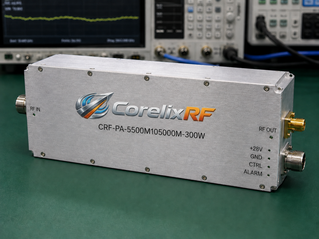
- Physical Mechanism: Increasing output power fundamentally lowers the optimal load impedance (Zopt) of the transistor. The original impedance matching network must be recalculated and re-routed; failure to do so causes severe RF energy reflection. Transitioning from pulsed to CW operation multiplies the average thermal dissipation exponentially, guaranteeing the original bias network will instantly burn out from current overload.
2. Thermal Management Restructuring
An RF amplifier’s continuous operation capability relies entirely on its thermal design. Taking a standard platform built for Forced Air Cooling and shoving it into a sealed, fanless liquid-cooled chassis completely destroys the intended Thermal Resistance Path.
- Engineering Standard: We must conduct new thermodynamic simulations and redesign the baseplate’s thickness and material (such as integrating copper-molybdenum alloys) to eliminate localized hotspots that cause premature device failure. This thermodynamic overhaul is the non-negotiable prerequisite for maintenance-free field deployments.
3. Severe Form Factor Shrinkage
Compressing a 4U standard amplifier into a 2U rack space involves much more than milling off excess aluminum. Altering the cavity dimensions shifts the internal microwave resonant frequencies, frequently neutralizing the original Electromagnetic Compatibility (EMC) shielding. Furthermore, forcing the Power Supply Unit (PSU) closer to the RF module inevitably introduces low-frequency spurious interference and ripple superposition across the transmitted signal.
The Impact of Redesign on Delivery and Acceptance
When requirements cross into the “Red Zone,” system integrators must allocate adequate time for proper redesign within their master schedules. CorelixRF’s custom manufacturing protocol adheres strictly to engineering truth: every redesigned circuit must pass a rigorous Factory Acceptance Test (FAT).
We refuse to supply unverified “paper parameters.” For all redesigned models, we provide comprehensive laboratory test evidence before shipment, including:
- Full-Band High/Low-Temperature Gain Curves: Proving that output field strength will not attenuate due to thermal gain drift under extreme environmental conditions.
- Full-Load Continuous Power Burn-In Testing: Validating the thermal equilibrium point of the new cooling system to guarantee lifecycle stability during unbroken operation.
- VSWR Protection Threshold Verification: Simulating real-world antenna impedance mismatches to prove the open/short circuit protection physically triggers, permanently mitigating RMA risks.
Conclusion
In RF power amplifier procurement and integration, attempting a “quick tweak” that violates physical boundaries is the genesis of an expensive disaster. Acknowledging the strict modification limits of standard platforms empowers procurement and quality departments to neutralize fatal system-level risks early in the planning phase.
If your system demands uncompromising field strength metrics and continuous operation reliability, do not trust theoretical catalog extrapolations. The correct protocol requires deep technical alignment with an actual RF manufacturing factory before any design drawings are frozen.
Uncertain about the parameters of your next RF chain project?
Submit your target frequency, output power, waveform type, and thermal constraints to CorelixRF and request a 48-hour engineering review. We will deliver a precise feasibility assessment and testing roadmap grounded entirely in laboratory data.
Define pulsed RF amplifier changes before mechanical work starts
For pulsed amplifier projects, provide pulse width, duty cycle, rise/fall time, peak and average power, blanking/control signals, protection timing and cooling constraints. These details decide whether a standard pulsed platform can be adapted safely.
Recommended next step: send the target band, output power, duty cycle, load condition, control interface, cooling limit and required FAT documents. CorelixRF can map this pulsed RF amplifier platform modification requirement to a standard platform or a controlled customization path.