
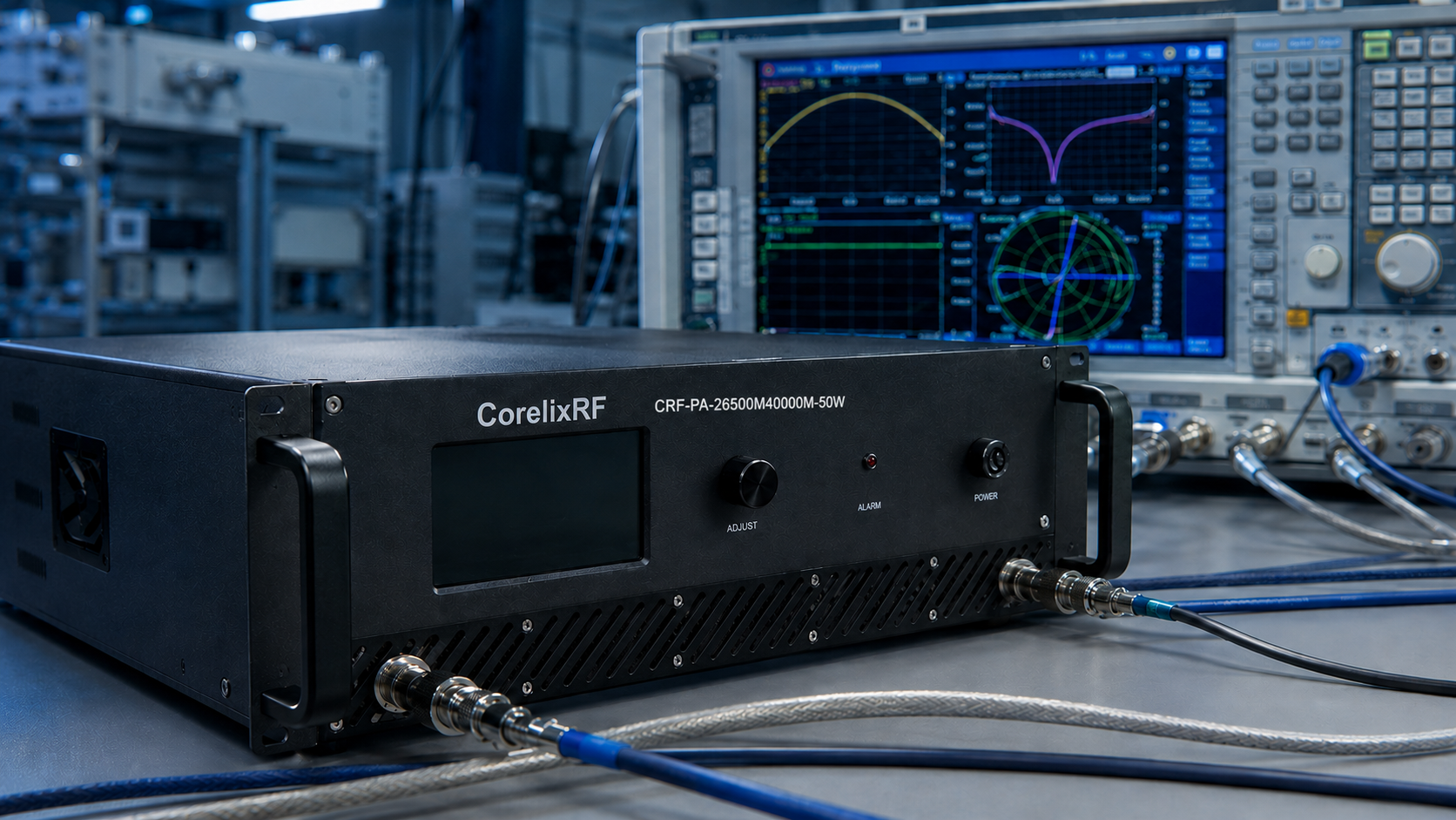
When procuring Radio Frequency (RF) power amplifiers, the most common project failure risks faced by system integrators and R&D engineers often stem from “purchasing directly based on the superficial parameters of a datasheet.” Many devices perform perfectly under an ideal 50-ohm load in the laboratory, but quickly experience power degradation, gain drift, or even final-stage component burnout under actual conditions of antenna impedance mismatch, continuous wave (CW) full-power operation, or excessive cabinet thermal resistance.
Move RF amplifier RFQ questions into a factory review path
For procurement teams, CorelixRF can review frequency range, power class, VSWR protection, thermal margin, FAT evidence, delivery documents and custom RF system risks before quotation.
The truth of engineering lies in physical mechanisms and actual lab test data, rather than maximum ratings on paper. To ensure your system integration passes acceptance testing the first time, and to obtain truly reliable test evidence and rapid response, CorelixRF has compiled the top 10 core technical questions most frequently asked by global customers when submitting a Request for Quote (RFQ).
Q1: Why does CorelixRF recommend an engineering review first, rather than directly buying standard catalog models?
- Engineering Pain Point: Standard datasheet parameters are measured under ideal environments (constant temperature, pure resistive load), whereas a customer’s actual link usually includes cable insertion loss, connector VSWR, and unforeseen thermal boundary conditions.
- CorelixRF’s Solution: Directly purchasing a standard model easily leads to system integration failure. We require confirmation of your actual system environment before quoting. Through our 48-hour engineering review, our technical team will evaluate the actual load VSWR, cabinet cooling margins, and control interface logic. This upfront physical parameter verification is the only rigorous path to avoid subsequent acceptance failures.
Q2: Will the amplifier burn out if the actual antenna or load Voltage Standing Wave Ratio (VSWR) is high?
- Engineering Pain Point: Impedance mismatch causes RF energy to reflect back to the amplifier’s output. The superimposed reflected power and forward power can cause drain voltage breakdown or excessive junction temperatures in field-effect transistors (like GaN/GaAs).
- CorelixRF’s Solution: Our module and system products employ physical hardware protection mechanisms tailored to their frequency band and power level. For example, we either use built-in ferrite isolators to absorb reflected power directly or utilize directional couplers to monitor reverse power in real-time. Once the VSWR exceeds a set threshold (e.g., 3:1), the system will automatically cut off or back off the RF drive within microseconds, ensuring the absolute safety of the hardware.
Q3: Your datasheet lists “Rated Power.” Is this Saturated Power (Psat) or Linear Power (P1dB)?
- Engineering Pain Point: Different manufacturers have inconsistent definitions of “power.” If a customer needs to amplify complex modulated signals with a high Peak-to-Average Power Ratio (PAPR) (such as OFDM), mistakenly using saturated power as linear power will result in severe Intermodulation Distortion (IMD) and spectral regrowth.
- CorelixRF’s Solution: In CorelixRF’s technical specifications, we explicitly distinguish between saturated output power and 1dB compression point power (P1dB). If your application is for communication systems, we provide Two-tone IMD test curves; if it’s for radar pulses, we provide peak power and pulse droop data. We never use ambiguous parameters to mislead your selection.
Q4: Can the amplifier operate stably 24/7 under Continuous Wave (CW) full power? How is the thermal design handled?
- Engineering Pain Point: RF power amplifiers are inherently heat-dissipating devices. Poor thermal design will cause the chip junction temperature (Tj) to exceed the safe critical point of 150°C-200°C, causing irreversible performance degradation (a sharp decline in MTBF).
- CorelixRF’s Solution: We conduct rigorous thermal simulations based on actual application conditions. Take the CRF-PA-26500M40000M-50W (covering 26.5 – 40 GHz, 50W output) as an example. For CW operation, we evaluate the baseplate thermal resistance, equip it with customized high-efficiency forced air-cooling fins, and embed temperature sensors. Once the internal temperature exceeds a threshold (e.g., 85°C), the amplifier automatically triggers Over-Temperature Protection (OTP) and reports a fault code.
Q5: How significant is the Gain Drift when the environmental temperature changes drastically?
- Engineering Pain Point: In wide-temperature environments, the carrier mobility of semiconductor materials changes, causing amplifier gain to fluctuate with temperature. Left uncontrolled, the RF system will lose its calibration baseline.
- CorelixRF’s Solution: For aerospace and field electronic warfare applications, we employ built-in Temperature Compensation Circuits and active bias control networks. This ensures that gain fluctuation over the entire operating temperature range (e.g., -40°C to +85°C) is tightly controlled within a ±1.5 dB to ±2 dB window. The factory provides full-temperature high/low thermal cycle test reports as proof.
Q6: Upon delivery, will you provide empirical test data that matches our usage conditions?
- Engineering Pain Point: Procurement departments fear suppliers making empty promises—delivering only a certificate of conformity without traceable lab test curves, turning FAT/SAT (Factory/Site Acceptance Testing) into a “blind unboxing.”
- CorelixRF’s Solution: Our factory deliverables include a complete test evidence package. Every amplifier comes with an independent test report corresponding to its serial number, covering small-signal S-parameters (S21, S11, S22), full-band power sweep, harmonics suppression, and spurious data. All test conditions (input drive level, test load impedance) are explicitly documented in writing to ensure data reproducibility.
Q7: Can the control and monitoring interfaces be customized for our cabinet system?
- Engineering Pain Point: When building large automated test racks, system integrators are often restricted by the amplifier manufacturer’s closed control protocols, causing software integration to take weeks.
- CorelixRF’s Solution: We support highly flexible monitoring integration. Standard units offer front panel displays and basic alarms, while custom-engineered versions can provide communication interfaces including RS485, LAN, and optional GPIB. We open up the underlying control protocol, supporting forward/reverse power reading, temperature monitoring, operating current monitoring, and remote RF Enable/Disable, seamlessly integrating with your host computer.
Q8: How is the broadband Gain Flatness guaranteed?
- Engineering Pain Point: In multi-octave broadband applications (like EMC testing), poor gain flatness results in an inability to achieve the required field strength at certain frequencies, while having excess power at others.
- CorelixRF’s Solution: We apply cascaded equalizers and impedance transformation topologies within our internal RF matching networks. Before leaving the factory, a Vector Network Analyzer (VNA) is used to sweep and tune the entire frequency band, ensuring a linear and smooth power output across the entire specified bandwidth (e.g., 2-18 GHz), avoiding noticeable gain ripples.
Q9: What is the Service Level Agreement (SLA) and RMA process? We need a rapid response.
- Engineering Pain Point: Overseas customers and system integrators worry most about sluggish supplier feedback and lengthy repair cycles when equipment fails, stalling the entire project.
- CorelixRF’s Solution: CorelixRF implements a direct connection mechanism to our original factory engineers. Upon receiving a customer’s fault report or log, our technical team will conduct preliminary data diagnostics within 24 hours and provide a clear resolution plan within 48 hours. Our modular design architecture significantly shortens the RMA (Return Merchandise Authorization) repair and calibration cycles.
Q10: What information do I need to provide in the RFQ to get an accurate technical evaluation and quote?
- Engineering Pain Point: Vague requirements (e.g., “Need a high-power amplifier”) lead to endless back-and-forth communication, wasting precious project time and ultimately resulting in mismatched selections.
- CorelixRF’s Solution: The most efficient communication is built on clear engineering boundaries. When submitting an RFQ, please ensure you provide these 5 key parameters:
- Operating Frequency Range (e.g., 26.5-40 GHz)
- Required RF Output Power (explicitly state Psat or P1dB, e.g., 50W Psat)
- Operating Mode (Continuous Wave [CW] or Pulse; if Pulse, provide duty cycle and pulse width)
- Control and Interface Requirements (connector type, communication protocol)
- Special Environmental Constraints (e.g., specific size limits, severe temperature requirements, or high VSWR tolerance)
Next Steps: Ensure Your Project Has No Blind Spots
Don’t let unverified datasheet parameters become a ticking time bomb in your RF system. Reliable integration requires real test evidence, rigorous physical verification, and transparent supplier communication. If your project is in the RF link evaluation phase, send us your system boundary parameters today.
👉 Take Action Now: [Submit your RFQ] or [Book a CorelixRF 48-Hour Engineering Review], and let our senior application engineers provide customized system matching recommendations and test verification plans.
Turn the article into a practical RFQ checklist
Before quotation, provide the target band, rated and linear power, duty cycle, load condition, control interface, cooling limit, protection behavior and required FAT documents. This reduces rework and avoids unclear amplifier promises.
Recommended next step: send the operating band, required output power, duty cycle, load condition, control interface, cooling limit, protection behavior and required FAT documents. CorelixRF can map this RF amplifier RFQ project risk control requirement to a standard platform, a controlled modification or a custom RF build.