
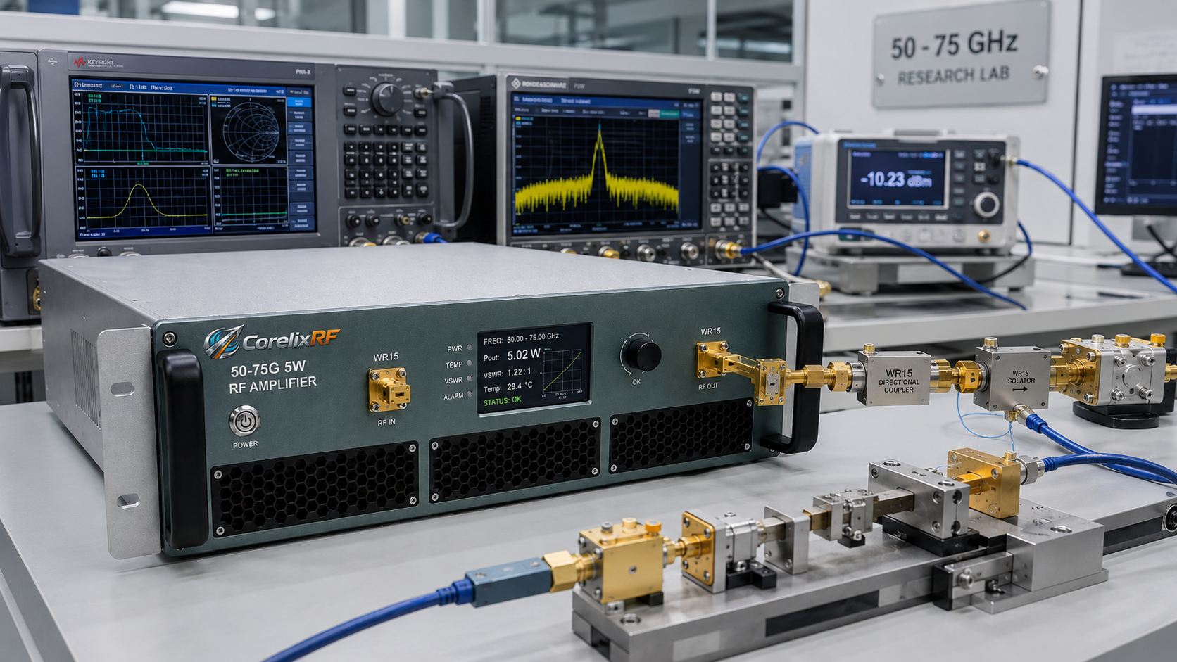
A 50-75 GHz 5W mmWave RF amplifier is usually selected after the engineering team has already learned that driver-level power is not enough. The next question is more practical: can the amplifier cover the required bandwidth, survive normal mismatch events, fit the control architecture, and move heat out of the system without making the RF chain harder to validate? CorelixRF CRF-PA-50G75G-5W is specified as a solid-state RF power amplifier covering 50 GHz to 75 GHz with 5 W rated RF output power and 37 dB minimum small-signal gain. It is intended for millimeter-wave test benches, high-frequency communications research, RF interference evaluation, and aerospace control paths where buyers need a defined platform rather than a loose collection of RF blocks.
For teams comparing a RF power amplifier against a custom bench assembly, the useful starting point is a disciplined specification review. Frequency range and output power matter, but so do gain flatness, connector format, remote control, protection behavior, cooling, and the acceptance data expected before shipment.
Why This Frequency Range Needs More Than a Power Number
The 50 GHz to 75 GHz range can expose weaknesses that are easy to hide at lower frequencies. Cable loss, fixture transitions, coupling factors, waveguide or coax limits, and load quality can all change the delivered power at the device under test. A 5 W amplifier should therefore be evaluated as part of the complete RF path, not as an isolated number on a quotation sheet.
The CRF-PA-50G75G-5W platform uses WR15 front-panel input and WR15 front-panel output. That interface detail should be reviewed with the rest of the test chain before the order is released. If adapters, directional couplers, filters, switches, or antenna feeds are part of the setup, their frequency rating and power rating should be confirmed in the same review. This is especially important when a broadband RF power amplifier is expected to support multiple test modes from one rack or module position.
Core Specifications for CRF-PA-50G75G-5W
The published product data lists 50 GHz to 75 GHz operating coverage, 5 W rated output power, 37 dB minimum gain, and gain flatness of -10 to +10 dB. The amplifier is designed for a 50 ohm RF environment. The input power limit should be treated as part of the drive chain design; attenuation, signal source leveling, and interlock logic should be planned before first RF power is applied.
RF performance also includes -20 dBc harmonics and -60 dBc spurious performance. These values help engineers decide where external filtering, shielding, or measurement margin may be required. In a production or compliance test environment, the amplifier is only one element in a larger uncertainty budget, so the project should define whether the important metric is amplifier output, forward power at a coupler, field level in a chamber, or received power at another calibrated point.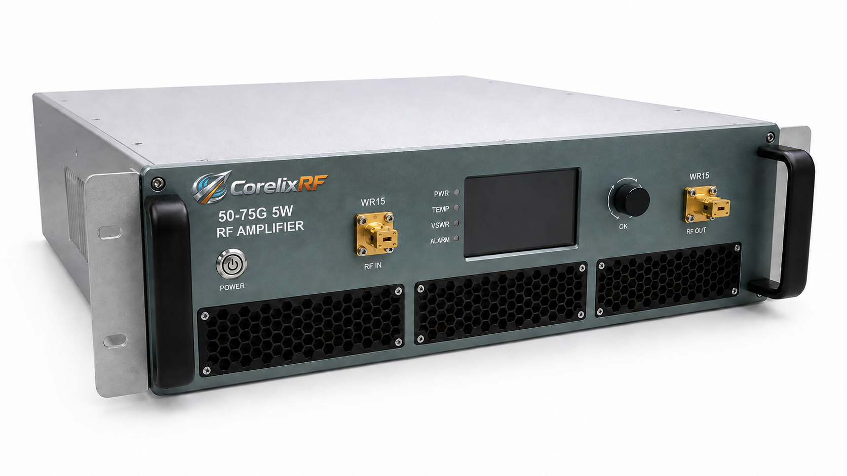
Control, Monitoring, and Protection Details
Control and diagnostics are part of the selection decision. CRF-PA-50G75G-5W supports RS485 and LAN, which makes it easier to integrate into automated benches, rack systems, and acceptance test procedures. The datasheet also describes real-time temperature monitoring and real-time current monitoring, with forward and reverse power monitoring available where specified or requested.
Protection functions are not a substitute for good RF practice, but they reduce integration risk. The available protection set includes alarm and fault protection functions, temperature monitoring and alarm behavior, current monitoring and alarm behavior, over-temperature protection, over-drive protection, over-voltage protection, and VSWR protection and alarm functions. For a GaN SSPA, these items should be reviewed alongside duty cycle, waveform type, cooling airflow, and expected mismatch scenarios.
Mechanical and Thermal Planning
The amplifier uses forced-air 19-inch 3U configuration and is specified for 0 to +50 C operating temperature. That makes mechanical planning a real engineering task, not a late enclosure decision. Air inlet clearance, exhaust path, rack spacing, ambient temperature, cable bend radius, and service access all affect whether the amplifier performs consistently during long tests.
A good RFQ should ask for the final mechanical drawing, control protocol, and relevant test data for the project configuration. If the amplifier will operate near rated output for long periods, the buyer should also define the duty condition and expected ambient environment. A rack-level microwave amplifier may meet the electrical target but still need careful airflow planning in a crowded integration bay.
Application Fit and Buying Criteria
The main applications listed for CRF-PA-50G75G-5W include test and measurement instrumentation, communication systems, RF interference or system-level testing, and aerospace control. Those categories are broad, so the procurement team should translate them into project-specific acceptance criteria. Examples include minimum output power across the band, gain flatness tolerance, connector type, remote-control commands, fault reporting, and the exact test point used for final acceptance.
Engineers planning EMC or immunity-related work can also compare the project requirements with CorelixRF guidance on EMC RF power amplifier selection. Teams working from a broader RFQ template can use the published RF amplifier RFQ checklist to define waveform, duty cycle, control interface, mechanical constraints, and environmental requirements before requesting a quote.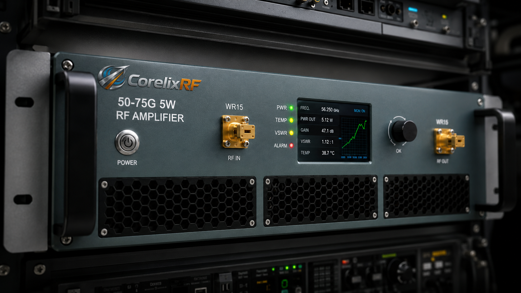
RFQ Checklist for This Amplifier
Before requesting pricing or lead time, prepare the target frequency range, required output power at the load or test point, waveform type, CW or pulsed operation, duty cycle, modulation format, allowable gain variation, control interface, cooling constraints, rack or module dimensions, and required documentation. If the amplifier is replacing an older unit, include the old gain, connector layout, remote-control expectations, and any known failure modes.
For CRF-PA-50G75G-5W, the RFQ should also confirm WR15 front-panel input and WR15 front-panel output, RS485 and LAN, AC 220 V ±10%, 50/60 Hz, forced-air 19-inch 3U configuration, and any required forward or reverse power monitoring option. This keeps the discussion focused on fit, risk, and verification instead of only comparing the headline wattage.
FAQ
Is CRF-PA-50G75G-5W a solid-state RF amplifier?
Yes. The datasheet describes it as a solid-state RF power amplifier platform using GaN technology for 50 GHz to 75 GHz operation.
What output power is specified?
The rated RF output power is 5 W. Final usable power at the DUT or antenna depends on the complete RF path, including cable, adapter, coupler, filter, and load losses.
What control interface should be planned?
The listed control interface is RS485 and LAN. If a project needs GPIB, LAN behavior, custom commands, or automated fault handling, those details should be confirmed during technical review.
Does the amplifier include protection features?
The available protection set includes alarm and fault functions, temperature and current monitoring, over-temperature protection, over-drive protection, over-voltage protection, and VSWR protection and alarm functions.
What should I send CorelixRF for a review?
Send the frequency range, required output power, waveform, duty cycle, control interface, mechanical constraints, cooling environment, and documentation needs. For a broader design discussion, review the 2-18 GHz broadband RF power amplifier guide and adapt the checklist to your band.