
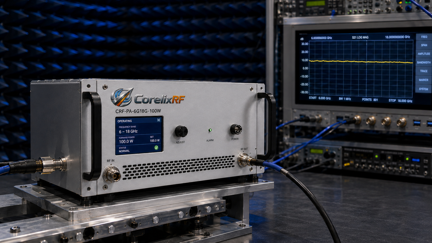
A 6-18 GHz microwave amplifier is often evaluated for RF test systems that need broad C-band, X-band, and Ku-band coverage in one platform. The wide bandwidth makes the amplifier attractive for laboratory validation, radar front-end evaluation, communication testing, and broadband RF stimulus, but it also makes selection more demanding. Across twelve gigahertz of bandwidth, output power, gain flatness, connector path, cooling, and control interface all need careful review.
CorelixRF presents the 6-18 GHz amplifier family with power classes from 10 W to 1000 W, gain range from about 40 dB to 60 dB, multiple connector paths, RS485 or LAN control options, and project-level customization. In article copy, model references should follow the CorelixRF naming style CRF-PA-6000M18000M-10W, CRF-PA-6000M18000M-50W, CRF-PA-6000M18000M-100W, CRF-PA-6000M18000M-200W, or the matching CRF-PA-6000M18000M-power value for the selected class. That range is broad enough that buyers should not treat the series as a single generic product. The correct configuration depends on the measurement objective and the physical system around the amplifier.
Why full-band behavior matters
The headline output power of a microwave amplifier does not automatically describe performance at both band edges. A test plan may need power at 6 GHz, 10 GHz, 14 GHz, and 18 GHz, but the amplifier’s usable output and gain flatness may vary by model. Before purchase, engineers should request datasheet curves or measured data where available, then compare that data with the minimum field strength, conducted power, or link budget required by the application.
This is especially important for RF testing and validation because calibration uncertainty can grow when the power stage has large gain variation. If the setup relies on repeatable power delivery across the full band, gain flatness and monitoring capability may be more important than choosing the highest watt class.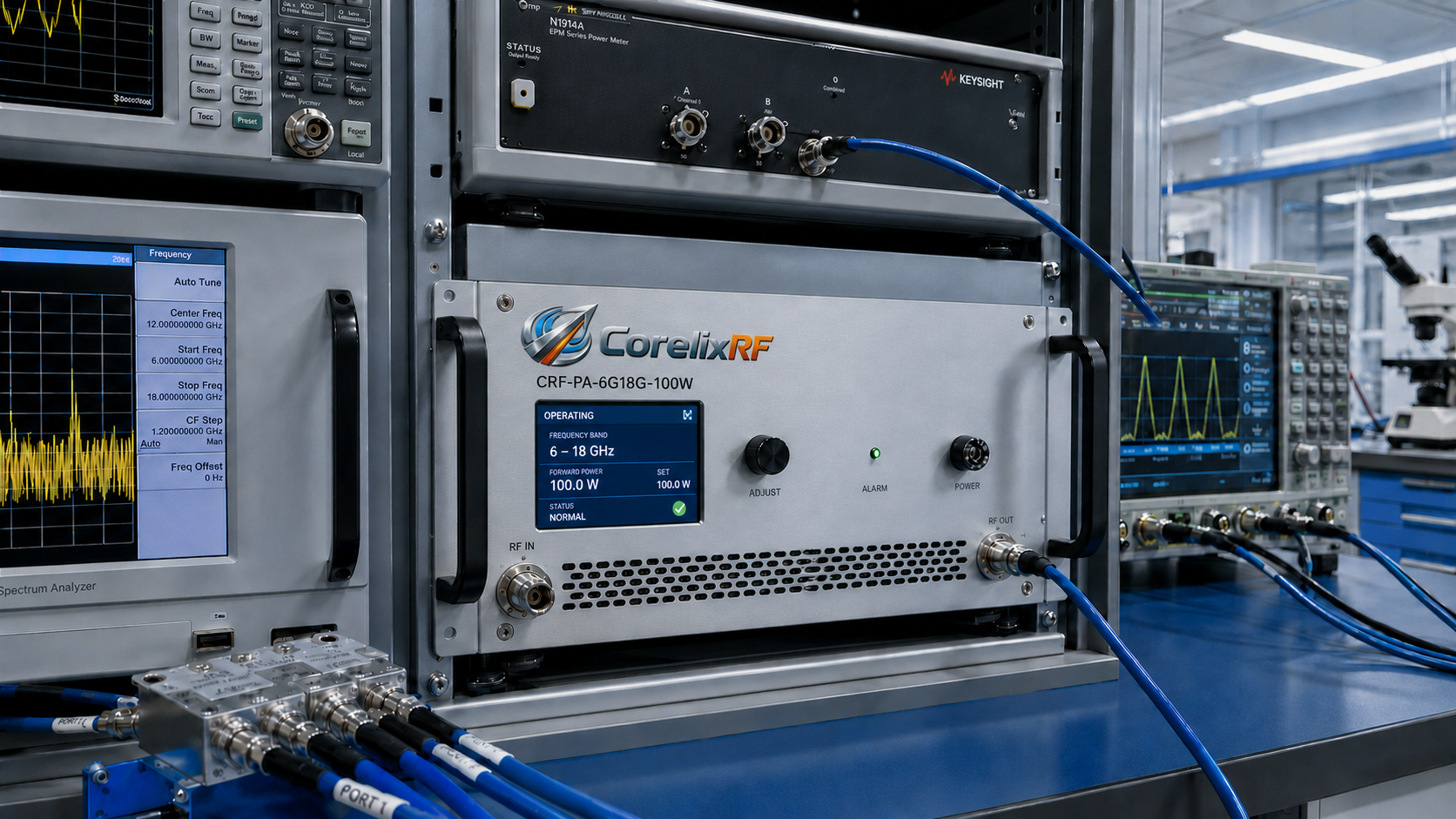
Key engineering checks
Output power class
CorelixRF lists datasheet-supported classes including 10 W, 16 W, 25 W, 30 W, 40 W, 50 W, 80 W, 120 W, 160 W, 200 W, 250 W, 300 W, 400 W, 500 W, and 1000 W. Each specific model should be written as CRF-PA-6000M18000M-power, for example CRF-PA-6000M18000M-50W or CRF-PA-6000M18000M-500W. Compact lower-power units may fit bench and driver-stage roles, while higher-power configurations may require rack-level airflow, installation review, and stronger control or monitoring requirements.
Gain flatness
The public 6-18 GHz page identifies flatness classes such as +/-4 dB, +/-5 dB, and +/-6 dB depending on model and power level. In a broadband test environment, this affects calibration, uncertainty, and power leveling. If the amplifier will be used with swept signals, ask whether measured gain and output data are available for the exact configuration.
RF connector and transition path
Connector selection changes mechanical layout and loss. CorelixRF references SMA-F, N-F, and WRD650 configurations across different power classes. The system designer should confirm input and output connector requirements, cable loss, waveguide transition needs, load condition, and rack layout before quotation.
Cooling and protection
High-power microwave amplifiers require thermal review. CorelixRF describes air cooling and built-in protection review that can include over-voltage, over-temperature, over-drive, and VSWR protection. The buyer should still define duty cycle, ambient temperature, airflow path, chassis space, and whether forward or reverse monitoring is required.
Control interface
Remote operation matters when the amplifier is part of an automated test bench. CorelixRF references RS485 and LAN options, with optional control requirements available for project review. If the amplifier must integrate into a larger test rack, command set, monitoring points, interlocks, and fault handling should be discussed before model confirmation.
Best-fit applications
The 6-18 GHz band is relevant for broadband microwave test benches, radar front-end validation, communication system testing, and custom RF system integration. It also fits buyers comparing compact microwave modules with rack-mounted systems. For a system that includes antennas or signal sources, CorelixRF’s RF front-end platform and custom RF systems pages are natural next-step references.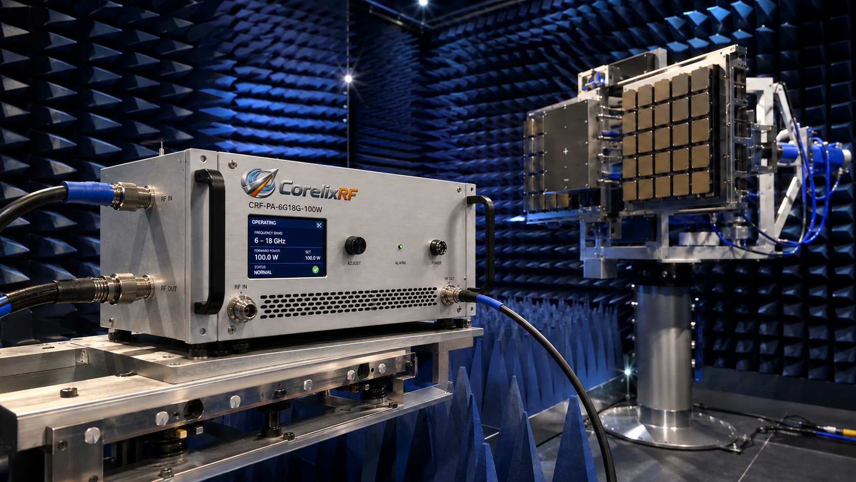
Suggested AIOSEO configuration
Set the focus keyword to “6-18 GHz microwave amplifier.” Use the SEO title and meta description from the front matter. Additional keywords should include “6-18 GHz RF power amplifier,” “broadband microwave amplifier,” “solid state microwave amplifier,” and “RF testing amplifier.” Use Article or BlogPosting schema plus FAQ schema.
FAQ
What should I confirm before selecting a 6-18 GHz microwave amplifier?
Confirm required frequency span, minimum output power across the band, gain flatness, RF connector path, duty cycle, cooling method, control interface, and test data requirements.
Is the highest power class always the best choice?
No. Higher power may require more rack space, airflow, supply planning, and protection review. Select the power class that matches the real test requirement with suitable thermal and control margins.
Can CorelixRF review custom connector or chassis requirements?
Yes. CorelixRF states that connector arrangement, cooling layout, power supply, monitoring, control interface, and mechanical integration can be reviewed by project.
Why does gain flatness matter in broadband RF testing?
Gain flatness affects calibration and repeatability across frequency. A flatter response can reduce correction burden and help engineers maintain more predictable power levels during swept or multi-band testing.