
OEM teams selecting a 30-512 MHz RF power amplifier usually need more than a catalog wattage value. The amplifier must fit the electrical platform, thermal path, enclosure space, connector layout, documentation workflow, and real operating mode of the system. In VHF/UHF projects, those details can decide whether a standard broadband module is suitable or whether a custom sub-band design should be reviewed.
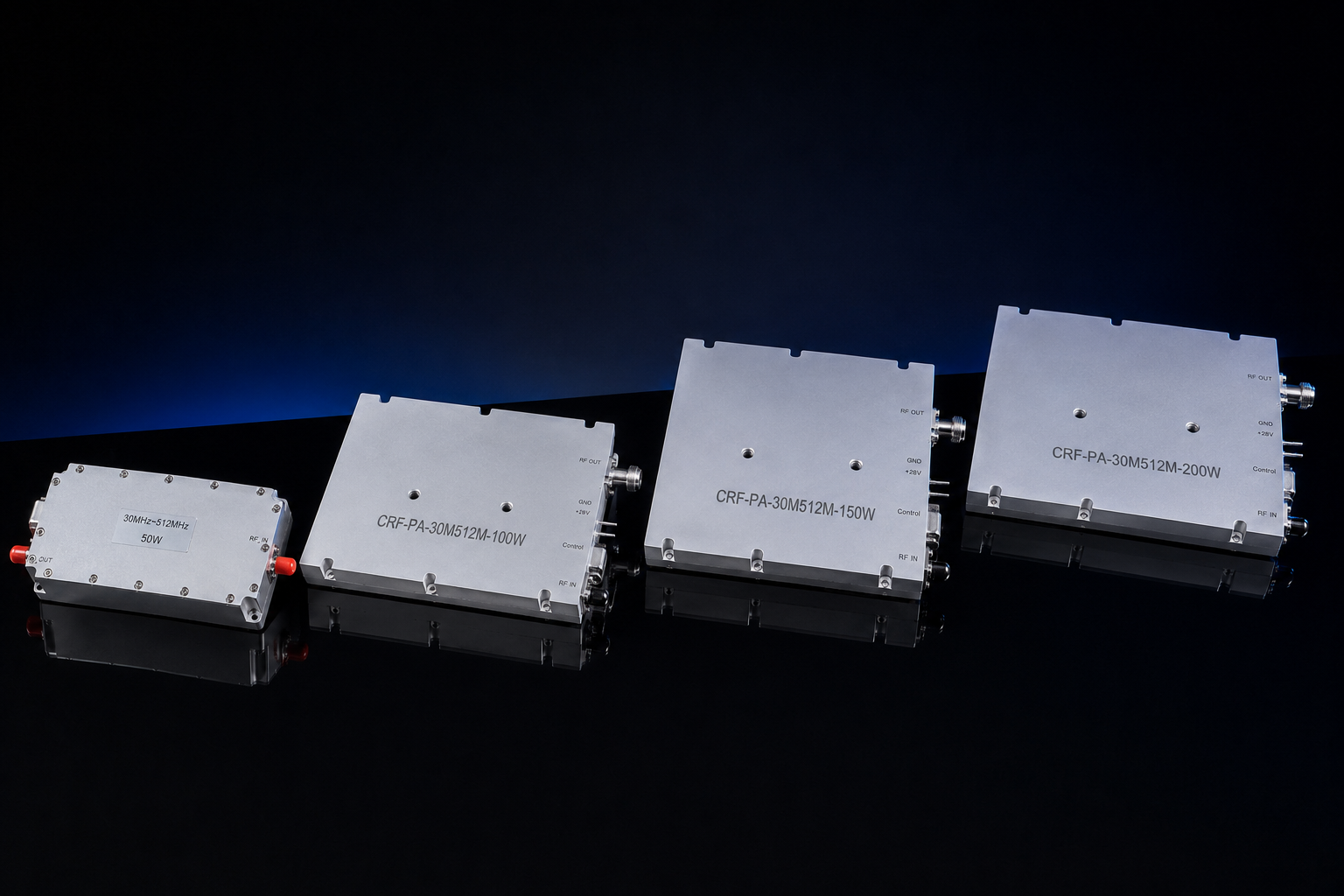
CorelixRF lists 30 W, 50 W, 100 W, 150 W, and 200 W standard models for the 30-512 MHz range. In article copy, model references should follow the CorelixRF naming style CRF-PA-30M512M-30W, CRF-PA-30M512M-50W, CRF-PA-30M512M-100W, CRF-PA-30M512M-150W, and CRF-PA-30M512M-200W. Public specifications show 28 VDC architecture, air cooling, SMA-F / N-F connector references, gain classes from about 45 dB to 53 dB depending on power level, and compact or larger mechanical envelopes by output class. This makes the platform relevant for laboratory RF evaluation, communication testing, broadband transmit chains, and OEM RF subsystem integration.
Why 30-512 MHz is a practical VHF/UHF platform
The 30-512 MHz span covers a wide VHF/UHF window without forcing the buyer to split the design into multiple narrowband amplifier stages. For test labs, that can simplify bench setups. For OEMs, it can reduce switching complexity and make the RF chain easier to document. However, broad coverage should still be compared against the actual project band. If the application only needs a smaller window, CorelixRF’s custom RF development path may be more appropriate.
The public model table identifies the CRF-PA-30M512M-100W class as a balanced standard platform for many integration projects, while lower-power models may suit compact lab evaluation and higher-power models may support demanding VHF/UHF transmit-chain work. Final selection should always be confirmed against duty cycle, thermal condition, supply budget, and load environment.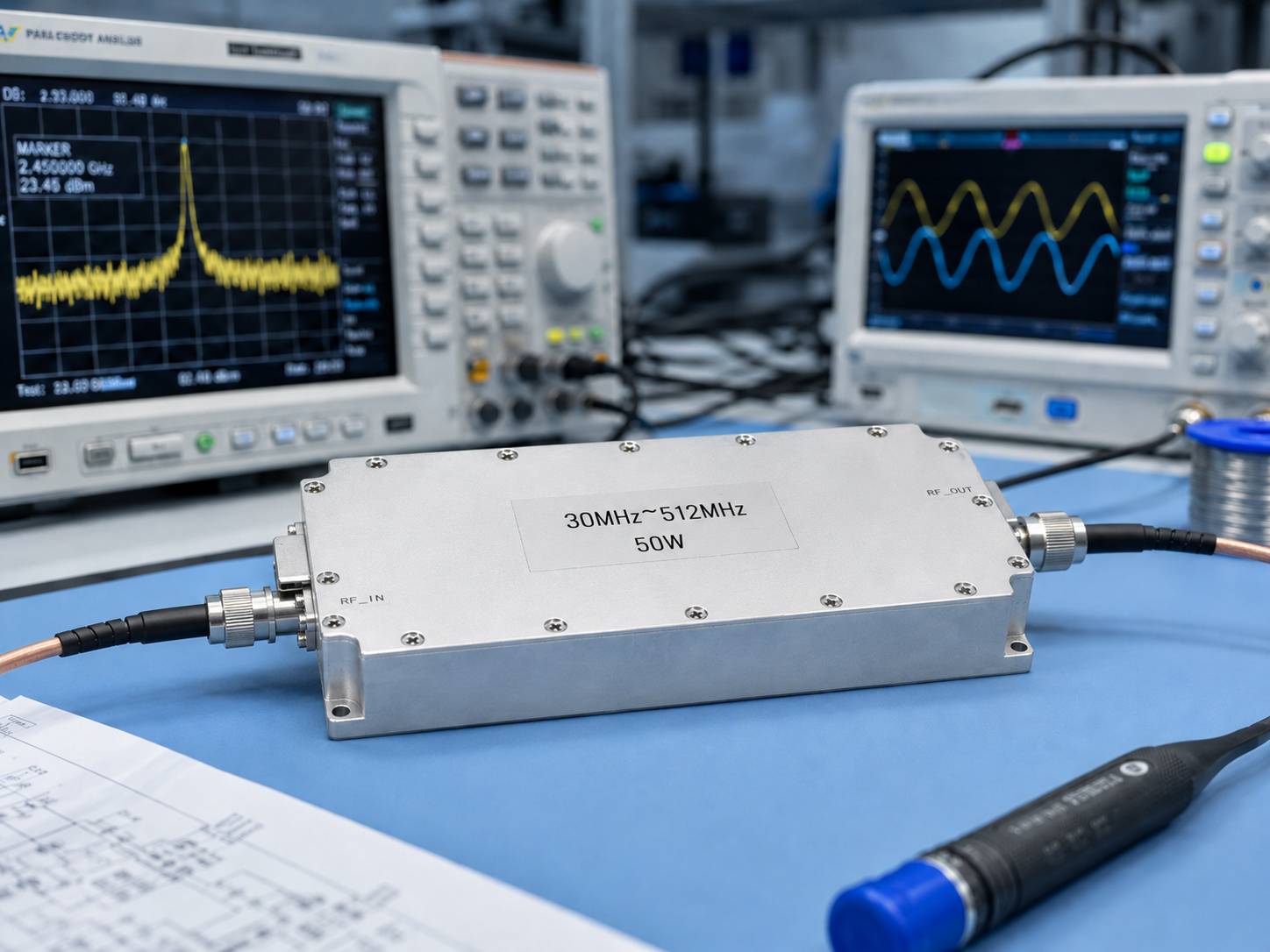
OEM integration factors to confirm
Supply and current budget
A 28 VDC architecture can simplify integration into industrial, vehicle-side, and embedded RF platforms. Still, current demand changes significantly by power class. CorelixRF’s public data lists maximum current references from lower single-digit amps for compact units up to much higher current requirements for 200 W operation. OEM designers should confirm PSU headroom, cable sizing, voltage drop, and protection strategy before committing to a model.
Mechanical envelope
CorelixRF lists compact 125 x 59 x 21.5 mm references for lower-power models and 200 x 158 x 25 mm references for higher-power models in this series. That difference affects mounting, airflow, connector clearance, service access, and enclosure layout. Mechanical drawings should be requested during technical evaluation when the amplifier will be installed inside a customer chassis.
Air cooling and duty cycle
All models in the 30-512 MHz public series use air cooling. For sustained operation, the system must provide adequate airflow over the module housing. The duty cycle, ambient temperature, output level, and enclosure design should be shared during engineering review. This prevents a common procurement problem: selecting by RF output while underestimating thermal load.
RF connectors and load condition
SMA-F / N-F connector references appear in CorelixRF’s public model table. The final connector path should be checked against cable size, output power, vibration environment, and antenna or load condition. If the amplifier will drive an antenna that may see mismatch, discuss VSWR concerns and protection behavior before order confirmation.
Where this amplifier fits
This VHF/UHF class fits wideband transmit chain projects, broadband communication system testing, EMC pre-compliance support, antenna evaluation, laboratory development, and custom transmit-chain work. It also fits buyers who want factory-direct technical communication instead of a simple reseller quotation.
For procurement teams, the most useful question is not “Which model is cheapest?” It is “Which model can be documented, cooled, mounted, powered, and validated in our actual system?” CorelixRF’s contact page asks for frequency range, output power, operating mode, load condition, connector preference, control interface, and application background because those inputs affect model fit.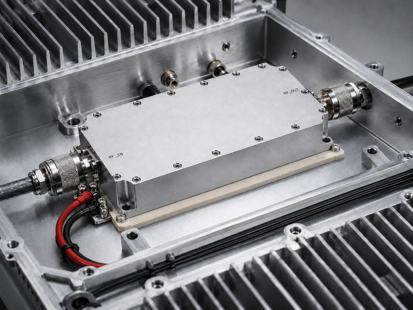
Suggested AIOSEO configuration
Set the focus keyword to “30-512 MHz RF power amplifier.” Use the SEO title and meta description from the front matter. Additional keywords should include “VHF UHF RF amplifier,” “broadband VHF amplifier,” “OEM RF amplifier,” and “28 VDC RF power amplifier.” Use Article or BlogPosting schema and add FAQ schema.
FAQ
What power classes are available for CorelixRF 30-512 MHz amplifiers?
CorelixRF’s public product page lists 30 W, 50 W, 100 W, 150 W, and 200 W standard models, with custom output targets available for engineering review.
Why is 28 VDC useful for OEM RF systems?
Many industrial and vehicle-side systems already use DC power architectures. A 28 VDC RF amplifier platform can simplify supply planning when current headroom and wiring are properly reviewed.
Can the 30-512 MHz amplifier be optimized for a narrower band?
Yes. If the real operating range is narrower than the full 30-512 MHz span, CorelixRF can review a sub-band design for gain flatness, efficiency, or thermal suitability.
What should be reviewed before mechanical integration?
Confirm module dimensions, connector locations, airflow path, mounting method, cable clearance, supply wiring, and whether mechanical drawings are required for internal design approval.