
Software-defined radio projects often begin with waveform flexibility, but the transmit-side hardware still has to meet ordinary RF engineering constraints: frequency coverage, output power, gain budget, input drive, cooling, protection behavior, connector planning, and test documentation. A 300-2700 MHz RF power amplifier can be a useful starting point when the system needs wideband coverage across UHF, L-band, and adjacent broadband RF test ranges without switching between several narrowband amplifier stages.
CorelixRF lists standard 300-2700 MHz amplifier platforms from 30 W to 200 W with 28 VDC supply architecture, typical gain classes from about 45 dB to 53 dB depending on output level, and engineering review for custom frequency subsets. In article copy, model references should follow the CorelixRF naming style CRF-PA-300M2700M-30W, CRF-PA-300M2700M-50W, CRF-PA-300M2700M-100W, CRF-PA-300M2700M-150W, and CRF-PA-300M2700M-200W. For buyers comparing a standard platform with a project-specific design, the right decision is rarely based on headline wattage alone. The better question is whether the amplifier can support the real SDR waveform, duty cycle, thermal path, source drive level, and load condition.
Why SDR transmit chains need amplifier review early
An SDR source can generate many waveforms, sweeps, hops, and modulation types, but that does not mean every RF power stage will behave the same way with each signal. A broadband amplifier selected only by frequency range and rated output may still create integration problems if the available drive level is too low, if gain flatness is not suitable for the test plan, or if the enclosure cannot remove heat under sustained operation.
For this reason, an SDR transmit chain should be reviewed as a full RF path. The source output level, pre-driver requirement, amplifier gain, coaxial loss, antenna or load match, duty cycle, and monitoring requirements all affect final model selection. CorelixRF’s SDR + amplifier integration page is a useful internal reference when the amplifier is part of a source-plus-PA system rather than a standalone procurement item.
Key selection factors for a 300-2700 MHz RF power amplifier
Frequency coverage and sub-band optimization
Full 300-2700 MHz coverage is attractive when one platform must support multiple test bands. However, if the project only uses a narrower operating window, a custom RF development review may improve practical fit. A narrower band can sometimes support better gain stability, efficiency, or thermal behavior because the design does not need to cover unused spectrum.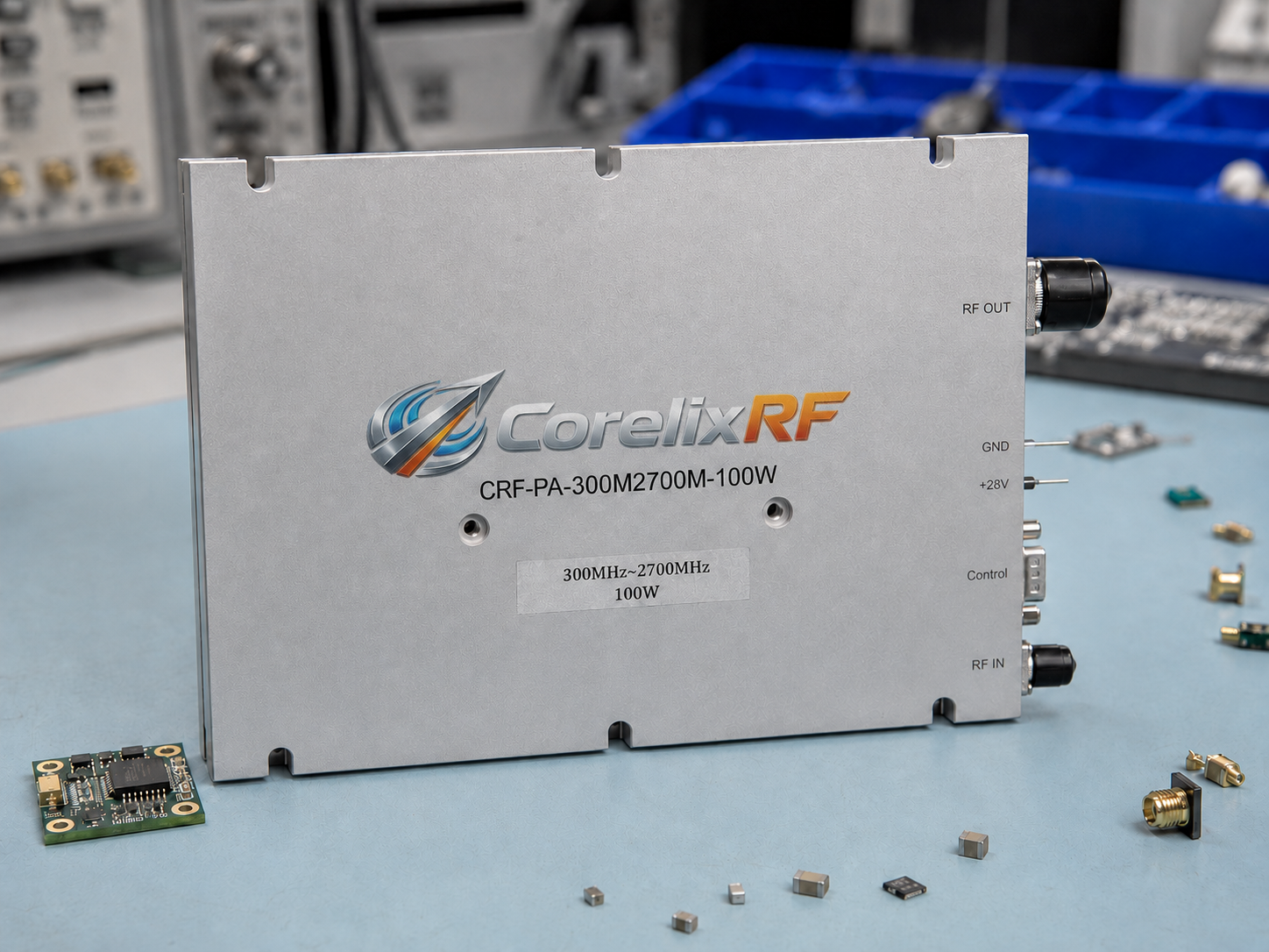
Output power and gain budget
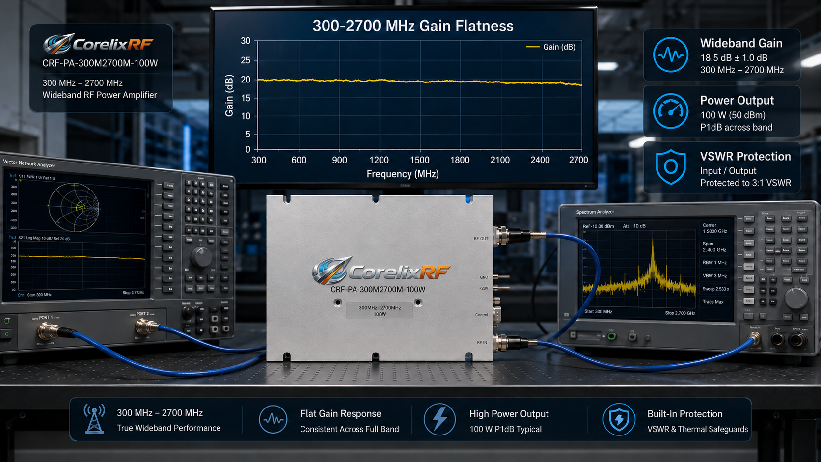
CorelixRF’s public model table includes 30 W, 50 W, 100 W, 150 W, and 200 W classes for this band. Use model names in the CRF-PA-300M2700M-power format, such as CRF-PA-300M2700M-100W, when referring to a specific power level. The listed gain range increases by power class, so the engineer should compare available SDR drive against the input level required to reach the target output. If the source cannot supply enough drive, a driver stage or different gain plan may be needed.
Thermal design and duty cycle
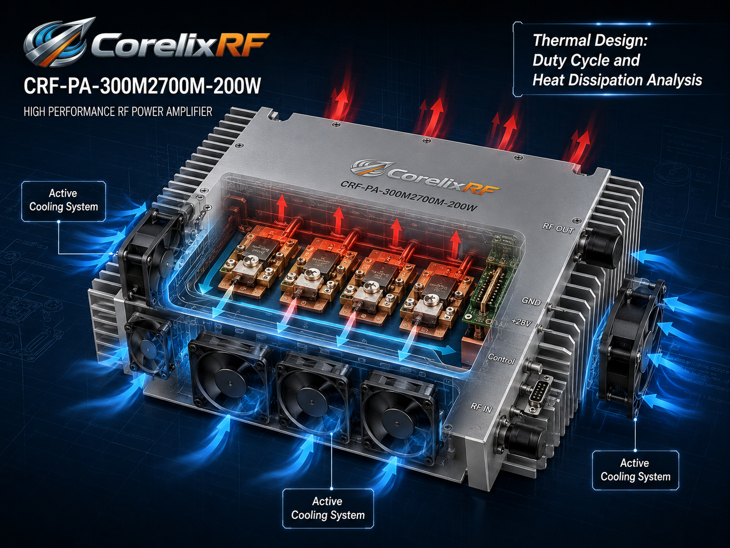
Thermal planning is where many SDR amplifier projects become more complex than expected. A waveform with high duty cycle creates a very different heat load from a short test burst. The amplifier should be reviewed against ambient temperature, mounting method, airflow or conduction path, enclosure constraints, and worst-case operating mode. For mobile or compact systems, thermal headroom is as important as RF headroom.
Protection and load condition
Broadband RF systems may encounter antenna mismatch, changing loads, or test setups that are reconfigured often. CorelixRF describes VSWR protection and validation checks for this series, including reflected-power protection review under open and short conditions. Engineers should still share the expected antenna, attenuator, coupler, or load condition before model confirmation.
Where this amplifier class fits
A 300-2700 MHz platform is relevant for wideband transmit chain projects, communication test platforms, laboratory RF evaluation, and SDR front-end power stages. It is especially useful when the system needs one amplifier family to cover several operating bands while keeping procurement and mechanical integration manageable.
For RF laboratories, the value is repeatable output across a wide range and access to test data during engineering review. For OEM projects, the value is the ability to discuss connector type, housing dimensions, control interface, cooling method, and sub-band tuning before order commitment.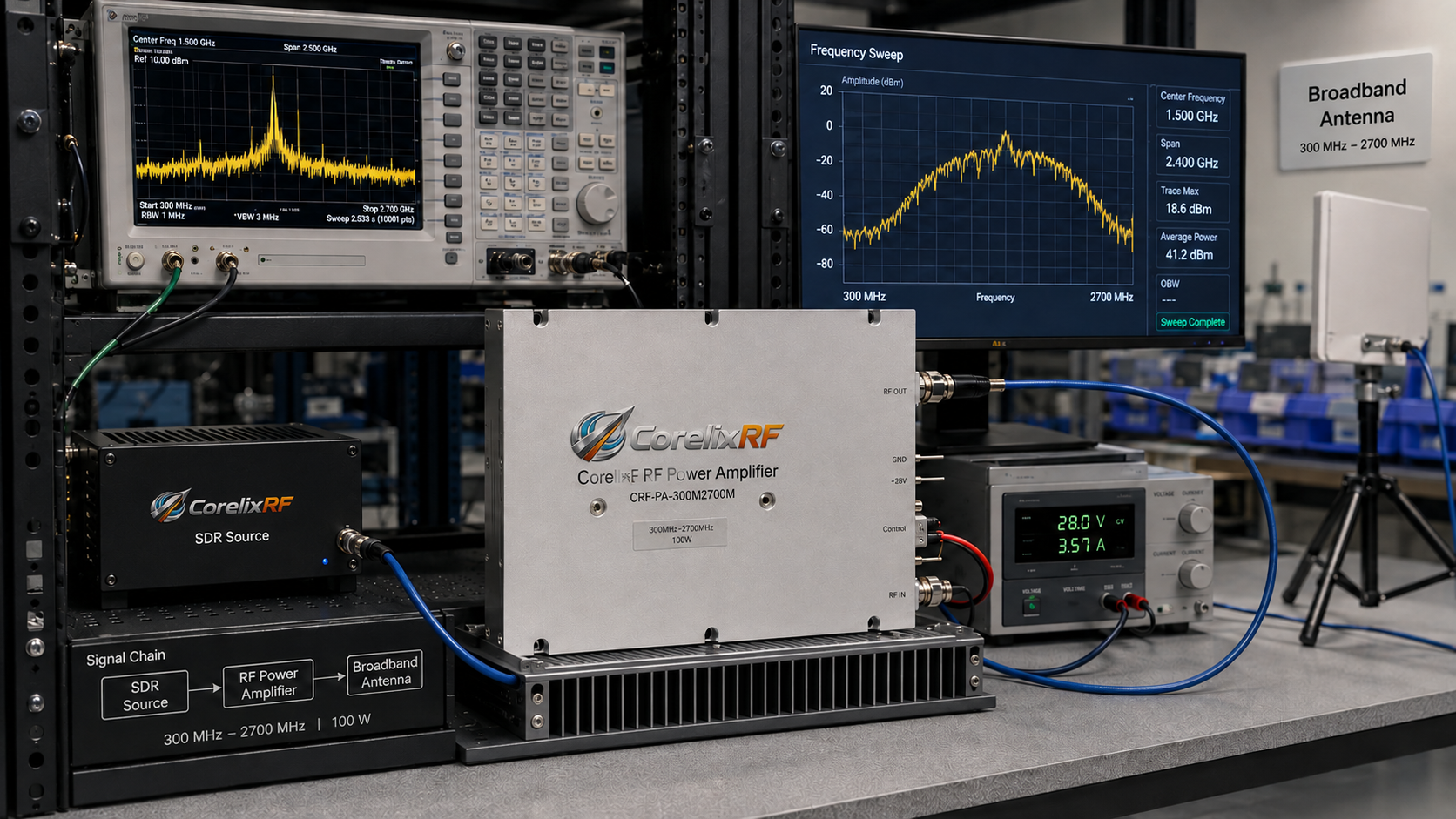
Suggested AIOSEO configuration
Use the SEO title “300-2700 MHz RF Power Amplifier for SDR Transmit Chains” and the meta description listed above. Set the focus keyword to “300-2700 MHz RF power amplifier.” Additional keywords should include “SDR RF amplifier,” “broadband RF power amplifier,” “GaN RF amplifier for SDR,” and “custom RF amplifier.” Use Article or BlogPosting schema, and add FAQ schema from the questions below.
FAQ
Is a 300-2700 MHz RF power amplifier suitable for SDR systems?
Yes, it can be suitable when the SDR transmit chain needs broadband coverage across UHF and L-band-related ranges. The source drive level, waveform type, duty cycle, gain budget, and thermal design should be reviewed before selection.
Should I choose full-band coverage or a custom sub-band?
Choose full-band coverage when flexibility matters more than peak optimization. If the project operates in a defined frequency window, ask CorelixRF to review a custom sub-band for gain flatness, efficiency, and thermal suitability.
What information should I provide before requesting a quote?
Provide frequency range, target output power, SDR output level, waveform type, duty cycle, load or antenna condition, supply constraints, cooling method, connector needs, and documentation requirements.
Can CorelixRF review SDR source and amplifier integration together?
Yes. CorelixRF supports SDR source module, RF amplifier, antenna, and RF chain compatibility review for engineering projects.