
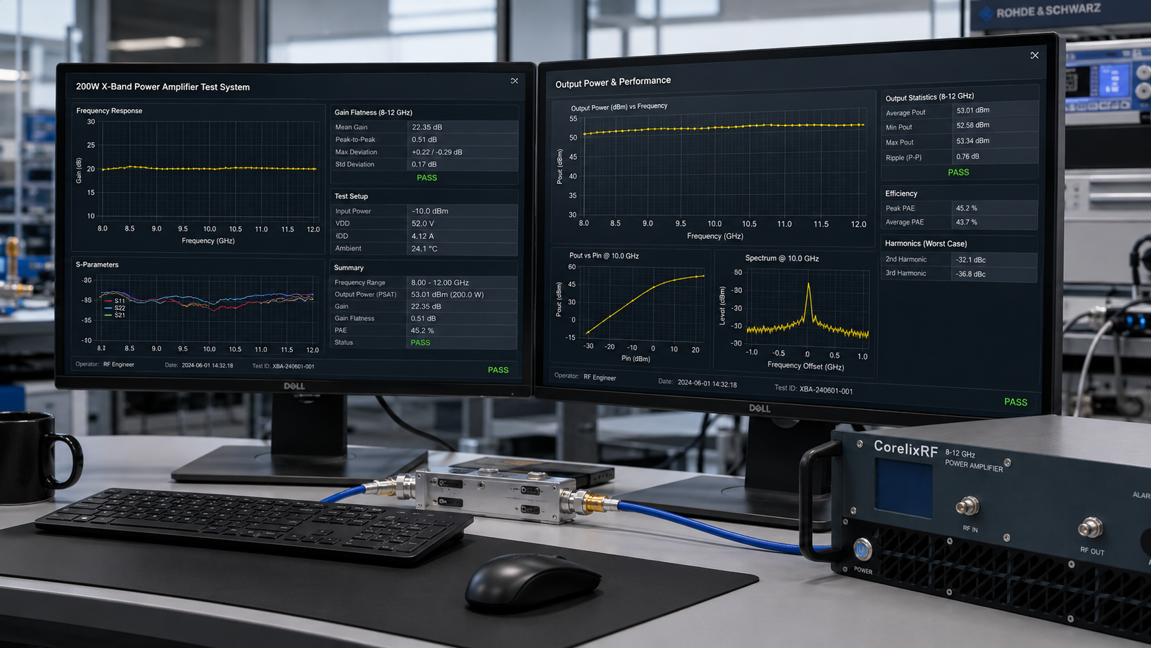
Engineers searching for a radar transmitter power amplifier usually need more than a headline output-power number. They need a solid-state amplifier that can be reviewed against frequency coverage, gain flatness, drive level, connectors, control interface, cooling, protection, and acceptance test evidence. The CorelixRF CRF-PA-8000M12000M-200W is based on the local product specification for 8-12 GHz operation and 200 W rated output power.
Where this 200 W amplifier fits in an X-band radar chain
The CRF-PA-8000M12000M-200W is intended for engineering review in X-band radar transmitter chains, radar test benches and microwave laboratory systems. Selection should be based on the complete RF path: waveform and operating mode, input drive, cable and fixture loss, load match, cooling, control and the required acceptance-test evidence.
The datasheet lists 8-12 GHz coverage, 200 W output power, 53 dB min. small-signal gain, and +/-3.5 dB gain flatness. Those values help estimate signal-generator drive level, cable and fixture loss, calibration margin, and expected delivered power at the load. When teams compare a broadband RF power amplifier with a custom configuration, they should evaluate the full RF chain rather than treating the amplifier as an isolated box.
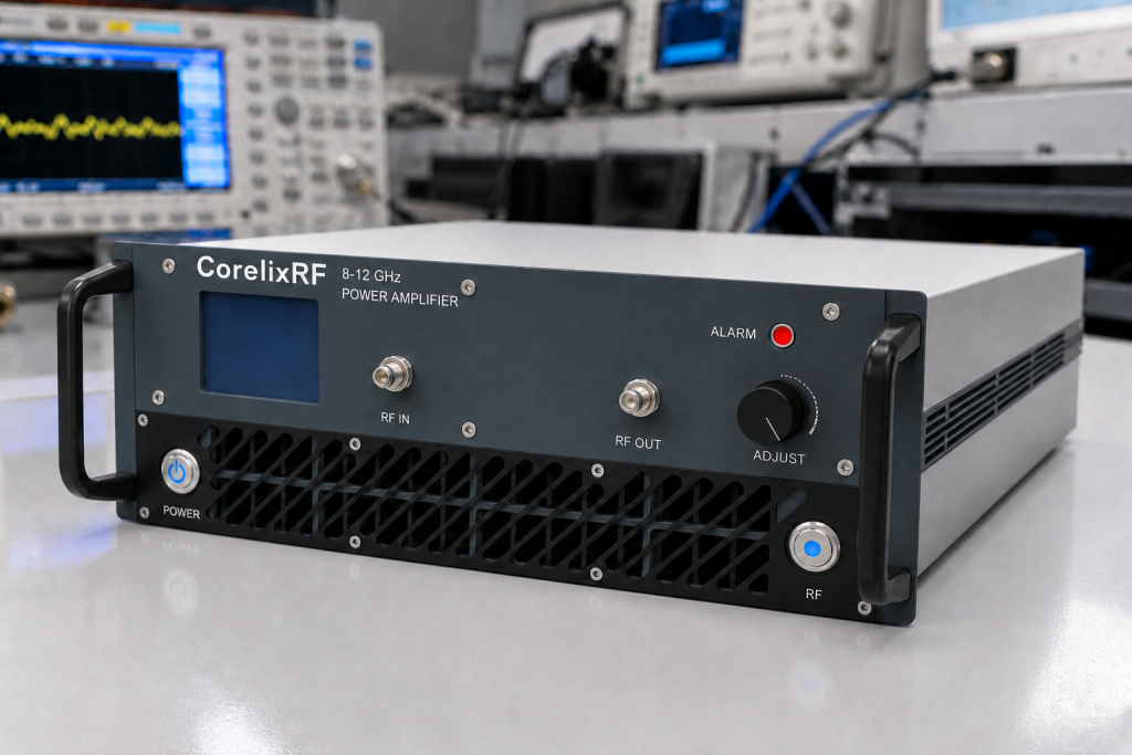
The RFQ should include waveform type, CW or pulsed operation, duty cycle, test duration, expected mismatch condition, ambient temperature, and preferred monitoring or control protocol.
How to evaluate output power and gain flatness
For CRF-PA-8000M12000M-200W, gain flatness should be reviewed with cable loss, coupler response, switch insertion loss, antenna or load behavior, and the test receiver setup. Output power should be measured with a defined frequency step, stable thermal condition, calibrated sensor, and known load match. The amplifier’s input limit of 0 dBm max. also matters; source startup routines and calibration scripts should not create accidental overdrive.
Integration notes for RF test and system platforms
The CRF-PA-8000M12000M-200W is relevant for X-band radar test systems, RF performance testing, communication-system verification, and microwave laboratory benches. Its N-Female input / N-Female output interface means the output path must be reviewed for power handling, insertion loss, return loss, and connector or waveguide handling. The N-Female RF path should be reviewed for X-band insertion loss, torque repeatability, and load power handling.
Thermal design is equally important. The datasheet identifies air cooling and mechanical form factor TBD in source data. Rack designers should verify inlet temperature, airflow direction, exhaust clearance, service access, and whether nearby equipment can recirculate heat. Module or waveguide installations should also review mounting, torque, alignment, and sensor access.
Control and protection should be part of the integration plan. The specification lists RS485 / LAN, real-time temperature monitoring, real-time current monitoring, and optional forward/reverse power monitoring where applicable. Protection functions include alarm and fault protection, over-temperature protection, over-voltage or over-drive related protection, and VSWR-related protection or alarm functions. A custom RF amplifier review can align these functions with the host controller before the mechanical design is finalized.
RFQ checklist for radar transmitter power amplifier
Before requesting a quote, prepare the target frequency range, required output power at the load, signal type, instantaneous bandwidth, duty cycle, drive level, load or antenna setup, mismatch exposure, rack or module limits, cooling conditions, control interface, and acceptance test method. If the project involves radar, SATCOM, RF laboratory testing, counter-UAS integration, or microwave test benches, note the legal and operational constraints that govern the test environment.
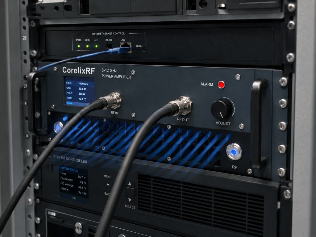
For higher-frequency comparison work, CorelixRF’s 18-40 GHz amplifier platform is a useful related page. For this specific article, however, the controlling facts remain the local datasheet for CRF-PA-8000M12000M-200W and the project review package supplied by CorelixRF.
Frequently asked questions
Is CRF-PA-8000M12000M-200W a solid-state power amplifier?
Yes. The datasheet describes CRF-PA-8000M12000M-200W as a GaN SSPA solid-state power amplifier for 8-12 GHz operation. Final configuration details should be confirmed during project review.
What is the specified output power?
The local datasheet lists 200 W rated output power. Delivered power in a real system depends on cables, waveguide or connector loss, load match, duty cycle, cooling, and measurement method.
What protection features should be reviewed?
Review over-temperature behavior, voltage and drive limits, VSWR-related protection or alarms, current monitoring, fault reporting, and how the host system should respond to each alarm.
Can CorelixRF customize this amplifier?
CorelixRF can review monitoring, control interface, mechanical constraints, waveform type, duty cycle, and environmental requirements during RFQ discussion.
Contact CorelixRF to request an RF amplifier review.
Choosing between the 200 W and 500 W 8-12 GHz amplifiers
The two CorelixRF models address different integration requirements. The 200 W model is the better starting point for radar transmitter evaluation, gain-flatness review and X-band test systems. The 500 W model is intended for projects that need higher RF output, WR90 waveguide integration and a larger thermal and electrical design margin.
| Model | Rated output | Primary review path | Related page |
|---|---|---|---|
| CRF-PA-8000M12000M-200W | 200 W | Radar transmitter and X-band test integration | Review the 200 W radar amplifier |
| CRF-PA-8000M12000M-500W | 500 W | High-power X-band and WR90 system integration | Review the 500 W X-band amplifier |
Final selection should confirm operating mode, required power at the system reference plane, input drive, load VSWR, RF interface, cooling, control and acceptance-test requirements.