
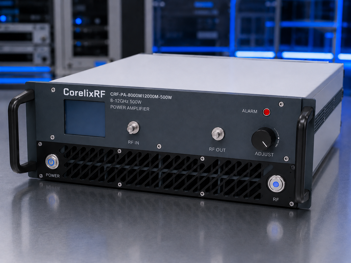
The CRF-PA-8000M12000M-500W is a CorelixRF GaN solid-state RF power amplifier specified for 8-12 GHz operation with 500 W rated output power. This article is written for engineers, RF lab managers, and procurement teams evaluating a specific amplifier model rather than browsing a generic product category. The goal is to turn the available specification data into a practical selection checklist for test benches, communication system evaluation, RF interference system-level testing, aerospace control system integration, and custom RF platform planning.
High-power X-band integration requirements
A 500 W amplifier must be reviewed as part of the complete X-band output path. The WR90 interface, waveguide transitions, directional couplers, switches, load or antenna match, cooling, AC supply and protection logic all affect the power available at the system reference plane. The RFQ should define these conditions before the mechanical and electrical configuration is released.
For this model, the extracted CorelixRF specification identifies 8-12 GHz frequency coverage, 500 W rated RF output power, 57 dB minimum small-signal gain, N-Female input and WR90 output, RS485 / LAN control, AC 220 V +/-10%, 50/60 Hz, and air cooling. These are the specification points that should appear in a quotation request and in any internal engineering comparison.
Core Specification Snapshot
Frequency Range and Power Class
The CRF-PA-8000M12000M-500W is specified for 8-12 GHz. The rated output power is 500 W. This places it in the high-power X-band waveguide-output amplifier category. Before purchase, define whether the power requirement is needed directly at the amplifier output or after downstream components. A directional coupler, switch matrix, waveguide transition, long coaxial run, chamber feedthrough, or test antenna can change the usable power at the device under test.
Gain, Drive Level, and Output Control
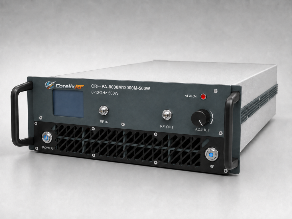
The specification lists 57 dB minimum small-signal gain and -3.5 to +3.5 dB gain flatness. The maximum input power is listed as 0 dBm in the extracted data. That means source planning is critical. A signal generator or SDR exciter should be paired with the correct attenuation and control procedure so the amplifier is not overdriven during startup, sweep setup, or waveform changes.
The model also lists a 20 dB gain control range. That is useful when the same RF chain must support multiple output levels without repeatedly changing external pads or source settings. Ask whether gain control is available through the quoted control interface and how it is reported in the control protocol.
RF Connectors and Mechanical Fit
The listed RF interfaces are N-Female input and WR90 output. The mechanical format is project-specific mechanical form factor marked TBD in the source data. Interface details can determine whether integration is straightforward or time-consuming. Coaxial configurations need attention to cable loss, connector rating, bend radius, and repeatable assembly. Waveguide-output configurations need flange review, output orientation, coupler placement, load rating, and fixture alignment.
Integration Notes for 8-12 GHz Systems
Cooling and Operating Environment
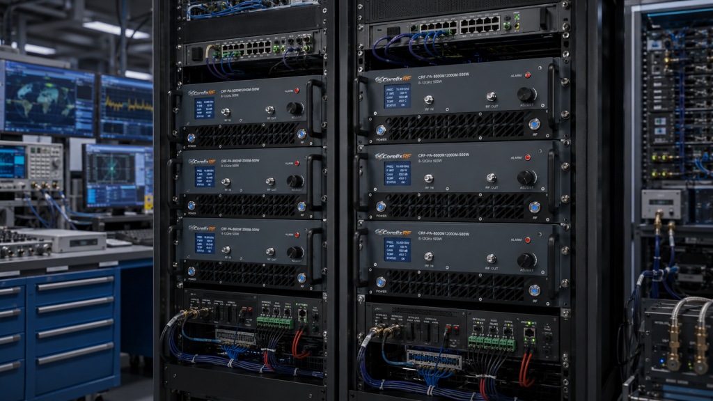
The specification lists air cooling. Cooling should be reviewed with the expected duty cycle, rack spacing, ambient temperature, and service access. For compact module formats, the system designer must provide a suitable thermal path. For rack units, airflow direction and intake clearance should be checked before the amplifier is installed near other heat-producing equipment.
Monitoring and Protection
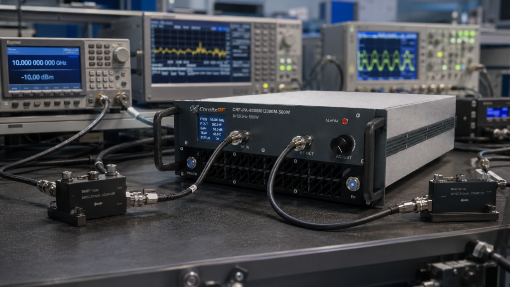
The extracted data references real-time temperature monitoring, real-time current monitoring, optional forward/reverse power monitoring, alarm and fault protection functions, over-temperature protection, over-drive protection, over-voltage protection, and VSWR protection or alarm functions. For high-power and microwave systems, these functions should be treated as engineering requirements. Ask which protections are active by default, which thresholds are fixed, which signals are available remotely, and how faults are reset.
Application Fit
For adjacent frequency and packaging options, review the RF power amplifier overview, the 6-18 GHz amplifier platform, or custom RF amplifier development. These pages help compare broader-band coverage and project-specific mechanical, connector, monitoring, or control requirements.
RFQ Checklist
A useful RFQ for this 8-12 GHz 500W RF amplifier should include the exact frequency range, required output power at the reference plane, waveform type, CW or pulse operation, duty cycle, input drive level, load or antenna VSWR expectation, output connector or waveguide details, cooling constraints, mechanical envelope, control interface, monitoring requirements, documentation needs, target quantity, and project timeline.
If the amplifier will support RF testing and validation , include the fixture and calibration assumptions. If the source is an SDR or software-defined waveform generator, include bandwidth, crest factor, modulation type, and expected duty profile, then review the SDR RF amplifier integration path before finalizing power level.
Mistakes to Avoid
Do not assume that all amplifiers in the same band share the same connector, cooling, control, or protection behavior. Do not compare a module and a rack amplifier only by output power. Do not omit the output reference plane. Do not claim EMC compliance, communication range, or field strength without a complete system calculation and test method. Use the confirmed model specification as the comparison baseline, then review installation-dependent requirements during the project evaluation.
FAQ
What model is covered in this guide?
This guide covers CRF-PA-8000M12000M-500W, specified by CorelixRF for 8-12 GHz operation with 500 W rated output power.
Choosing between the 200 W and 500 W 8-12 GHz amplifiers
The two CorelixRF models address different integration requirements. The 200 W model is the better starting point for radar transmitter evaluation, gain-flatness review and X-band test systems. The 500 W model is intended for projects that need higher RF output, WR90 waveguide integration and a larger thermal and electrical design margin.
| Model | Rated output | Primary review path | Related page |
|---|---|---|---|
| CRF-PA-8000M12000M-200W | 200 W | Radar transmitter and X-band test integration | Review the 200 W radar amplifier |
| CRF-PA-8000M12000M-500W | 500 W | High-power X-band and WR90 system integration | Review the 500 W X-band amplifier |
Final selection should confirm operating mode, required power at the system reference plane, input drive, load VSWR, RF interface, cooling, control and acceptance-test requirements.