
Failure-mode review
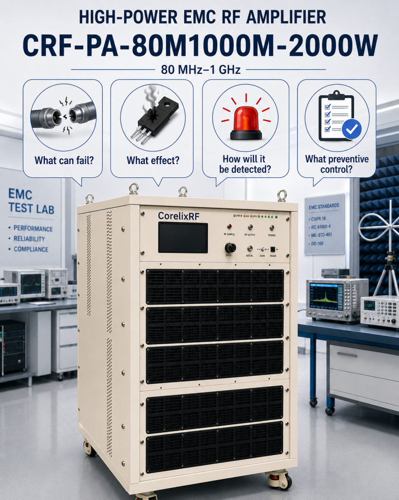
The CRF-PA-80M1000M-2000W can be assessed through failure modes rather than through a catalogue narrative. For the 80 MHz-1 GHz EMC RF amplifier / 2000 W use case, the review asks four questions: what can fail, what effect will it have on the result, how will it be detected, and what preventive control belongs in the project file?
The intent is prevention. It does not assume that any protection option or system outcome exists beyond the configuration confirmed for the project.
The CRF-PA-80M1000M-2000W is specified as a LDMOS solid-state platform covering 80 MHz-1 GHz EMC RF amplifier with 2000 W rated output. That combination should be read as an engineering starting point, not as permission to assume a complete system outcome. This acceptance brief explains how to turn the published band and power class into a useful request, installation plan, and acceptance record without claiming certifications, availability, or application results that have not been confirmed for the project.
Failure mode 1 — undefined operating point
Write down the actual frequencies inside 80 MHz-1 GHz EMC RF amplifier, not merely the broadest sweep a source can produce. Include CW or modulation details, target output level at the chosen reference plane, run time, source maximum, and the downstream load or antenna condition. A good request distinguishes a normal operating point from edge-of-band, warm-up, or fault-test conditions. This protects the test schedule from a common error: measuring at a connector while specifying power at a remote fixture.
For a continuous or swept application, record dwell time, leveling approach, and the frequency step or sweep rate. These variables affect how useful a nominal power figure is in a real rack. The purchase file should name the frequency points that matter, rather than importing a generic requirement from another program.
Failure mode 2 — uncontrolled RF path
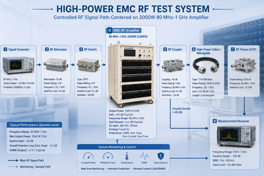
Sketch every item from signal generator to load: source, attenuation, switching, amplifier, coupler, cable or waveguide, fixture, and measurement receiver. Mark the power rating, frequency coverage, and expected loss of each item. The amplifier may be appropriate for the band while an adapter, coupler, load, or cable is not. Link-budget arithmetic and a defined reference plane make comparison between RF amplifier proposals more meaningful.
Specify what happens during enable, disable, and an abnormal condition. A source limit and a repeatable startup sequence are especially important for a high-gain solid-state design. Ask for the available control, monitoring, and protection behavior for the selected configuration, then decide how the test software or operator will respond. Do not assume optional monitoring or a project-specific interface is standard unless it is confirmed in the quotation.
Failure mode 3 — thermal or access constraint
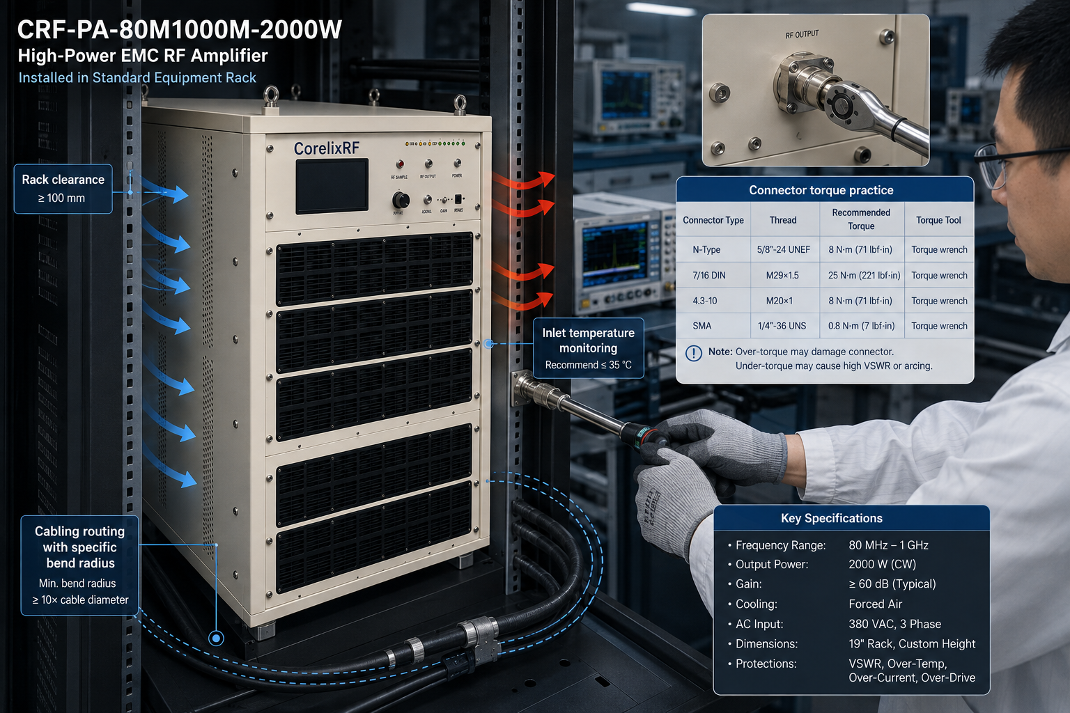
Cooling is part of RF performance planning. State the available rack clearance, inlet temperature, nearby heat sources, supply arrangement, cable routing, service access, and whether the installation is laboratory, vehicle, shelter, or OEM equipment. For coaxial systems, cable bend radius, connector torque practice, and safe access to high-power loads should be included in the installation procedure.
A short thermal acceptance run should record frequency, source level, output measurement, run duration, temperature indication if available, current indication if available, and any alarm state. The purpose is not to manufacture a pass result; it is to establish repeatable conditions that a future operator can reproduce. The CorelixRF EMC and broadband amplifier context is useful when choosing the closest platform, but final integration still needs the project data.
Failure mode 4 — missing acceptance evidence
A practical RFQ lists the model under review (CRF-PA-80M1000M-2000W), desired frequencies, output target and reference plane, waveform, source capability, load condition, cables, couplers, adapters, and fixture path, cooling and rack constraints, control preference, alarm expectations, and requested acceptance data. Ask which values are confirmed standard specifications and which need engineering review. This avoids treating a family description as a promise of an unquoted option.
Use measured data in the format the project can actually consume. A test team may need tabulated frequency points, gain or output data, a thermal run record, harmonic or spurious information appropriate to the application, and documentation of protection checks. A procurement team may additionally need an outline drawing, interface list, delivery terms, and a clear list of exclusions. Keeping these requests separate makes them easier to evaluate.
Residual-risk decision
Choose this high-power EMC amplifier direction when the required band and output class align with 80 MHz-1 GHz EMC RF amplifier and 2000 W, and when the surrounding RF chain can safely support it. Escalate to a custom review when a nonstandard frequency window, output interface, enclosure, control protocol, cooling method, or acceptance sequence changes the integration problem. A custom request is strongest when it begins with evidence rather than a vague request for “more power.”
The same discipline helps comparison shopping. Compare usable band, operating conditions, interface assumptions, thermal boundary, protection behavior, and requested test evidence—not only the largest headline wattage. This approach is suitable for lab integration, RF front-end development, EMC or communication test setups, and engineering evaluation where the claimed system performance must remain traceable to the actual chain.
FMEA close-out
The review is complete when each significant failure mode has an owner, a detection method, and a preventive control. If a control depends on a project-specific option, list it as open rather than implying that it is included.
Engineering references
Use the broader RF power amplifier, high-frequency RF capability, RF testing and validation, RF front-end platform, and custom RF development resources to route an RFQ to the closest standard platform or a project-specific review.
FAQ
What frequency range is listed for CRF-PA-80M1000M-2000W?
The local product specification identifies 80 MHz-1 GHz EMC RF amplifier.
What output power is listed?
The product specification identifies 2000 W rated output for this model class; final operating conditions should be confirmed in the quotation and test plan.
What should be included in an RF amplifier RFQ?
Include frequency points, waveform, output reference plane, source level, load, interfaces, cooling constraints, control needs, and acceptance data.
When is a custom RF amplifier review appropriate?
Use a custom review when standard frequency, interface, enclosure, cooling, control, or test requirements do not match the project.