
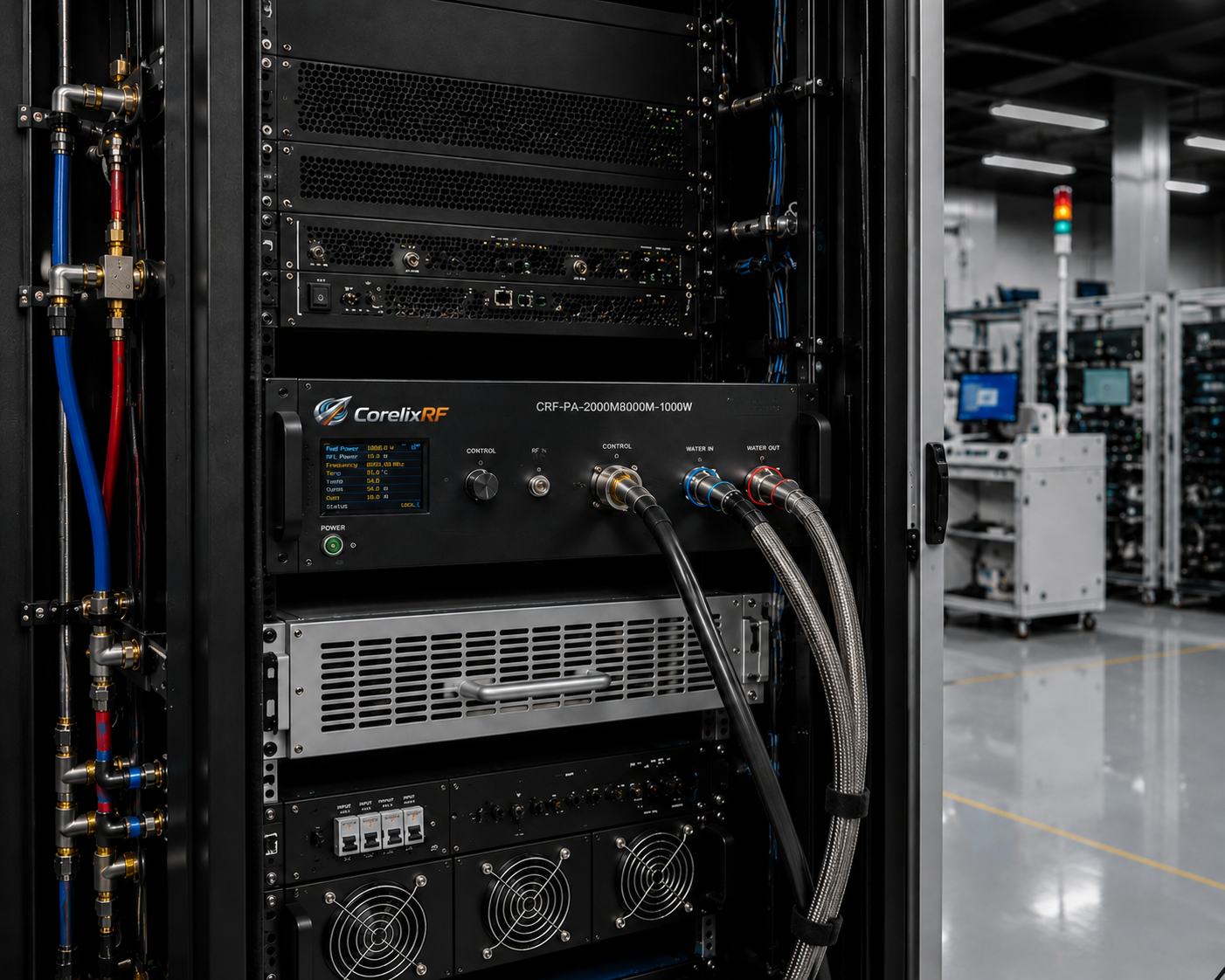
Relevant CorelixRF Products
| Product reference | Frequency range | Output power | Gain | Integration notes |
|---|---|---|---|---|
| CRF-PA-2000M8000M-1000W | 2-8 GHz | 1000 W | 60 dB min. | N-Female input, 7/16 output, RS485/LAN, water cooling |
Cooling Is a Selection Parameter, Not an Afterthought
A 2-8 GHz broadband RF power amplifier can sit at the center of many microwave test systems: communication payload simulation, RF stress testing, component qualification, broadband interference testing, and system-level verification. Because the amplifier covers a wide band and can operate at high output power, cooling should be treated as a core specification. It affects cabinet size, facility readiness, acoustic behavior, service access, operating duty, and long-term repeatability.
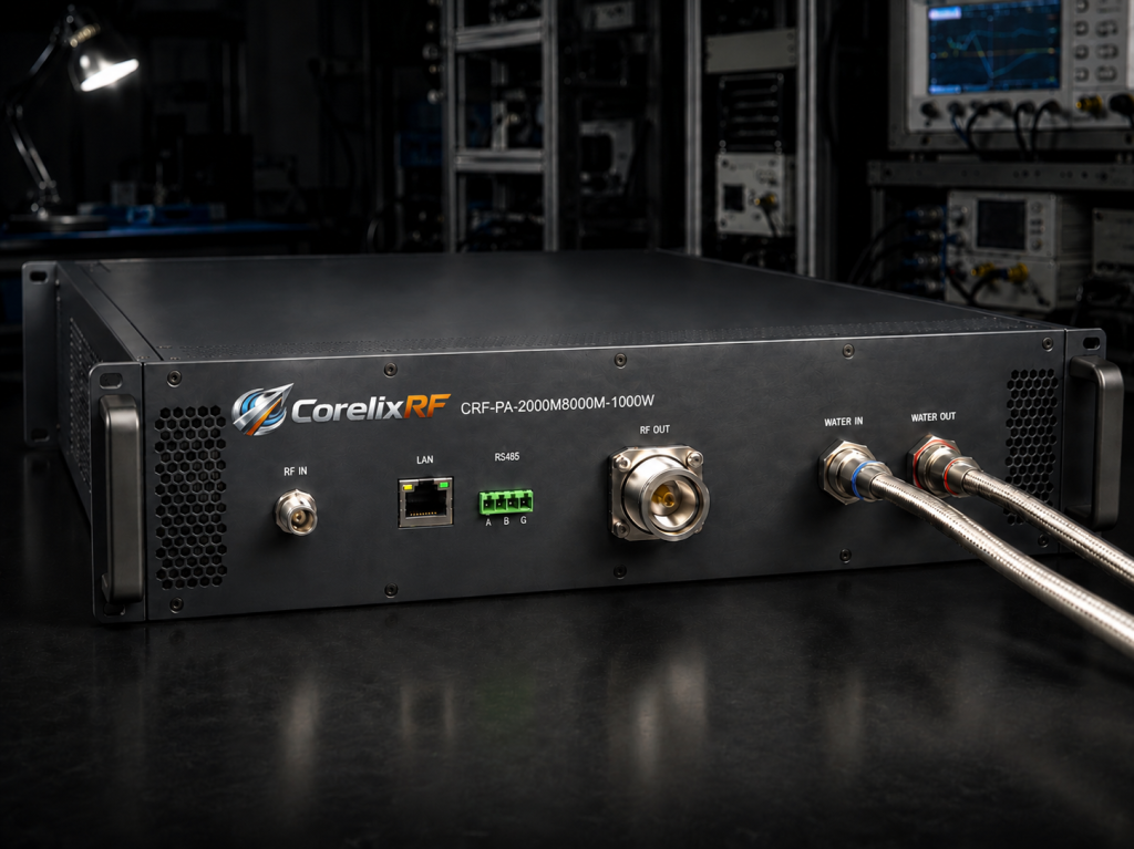
CorelixRF source specifications list the CRF-PA-2000M8000M-1000W as a GaN solid-state RF power amplifier covering 2000 MHz to 8000 MHz with 1000 W rated output power and 60 dB minimum small-signal gain. The referenced liquid-cooled configuration lists an N-Female input, 7/16 output, RS485/LAN control, AC 220 V +/-10% at 50/60 Hz, 0 to +50 C operating temperature, water cooling, temperature/current monitoring, optional forward/reverse power monitoring, optional input power detection, and protection functions including temperature alarm, current alarm, over-drive protection, and optional power monitoring.
When Liquid Cooling Makes Sense
Liquid cooling is often considered when the amplifier must deliver high output power over long operating periods, when the cabinet footprint needs to be controlled, or when heat must be moved away from a crowded equipment area. In a 1000 W high power broadband amplifier, the thermal plan can define whether the system behaves consistently during long sweeps.
The tradeoff is facility complexity. Liquid-cooled systems require coolant routing, leak planning, maintenance access, and procedures for startup and shutdown. The procurement package should not only ask for frequency and output power; it should also describe duty cycle, expected test duration, ambient temperature, rack position, and service constraints. That lets the amplifier configuration be reviewed against the real installation.
Frequency Coverage and Gain Flatness
The 2-8 GHz range covers a large portion of S and C band applications. It can reduce the need for multiple narrower amplifiers, but the wider the band, the more important gain flatness and calibration become. The source data lists gain flatness of -4 to +4 dB and gain control range up to 20 dB. Engineers should decide how correction will be applied: source leveling, amplifier gain adjustment, external attenuation, or software correction tables.
A 2-6 GHz amplifier may be a better fit if the project does not need coverage to 8 GHz. Conversely, if the upper range is important, a 2-8 GHz platform can reduce switching complexity. The right choice depends on required frequency points, output power, harmonic requirements, and how often the test setup must change bands.
RF Interfaces and Load Planning
The listed RF connectors are N-Female input and 7/16 output. This combination is common for high-power microwave work, but the rest of the path must be rated accordingly. Engineers should verify cable assemblies, adapters, directional couplers, loads, antennas, and switch matrices. The amplifier output connector should not be adapted repeatedly unless the added loss, mismatch, and power rating are fully understood.
For test platforms, a GaN RF amplifier is often connected to multiple downstream configurations over its life. That makes interface documentation important. A lab should keep a short approved-accessory list for high-power cables, loads, couplers, and adapters. This is a practical way to reduce accidental mismatch and overheating.
Controls and Protection
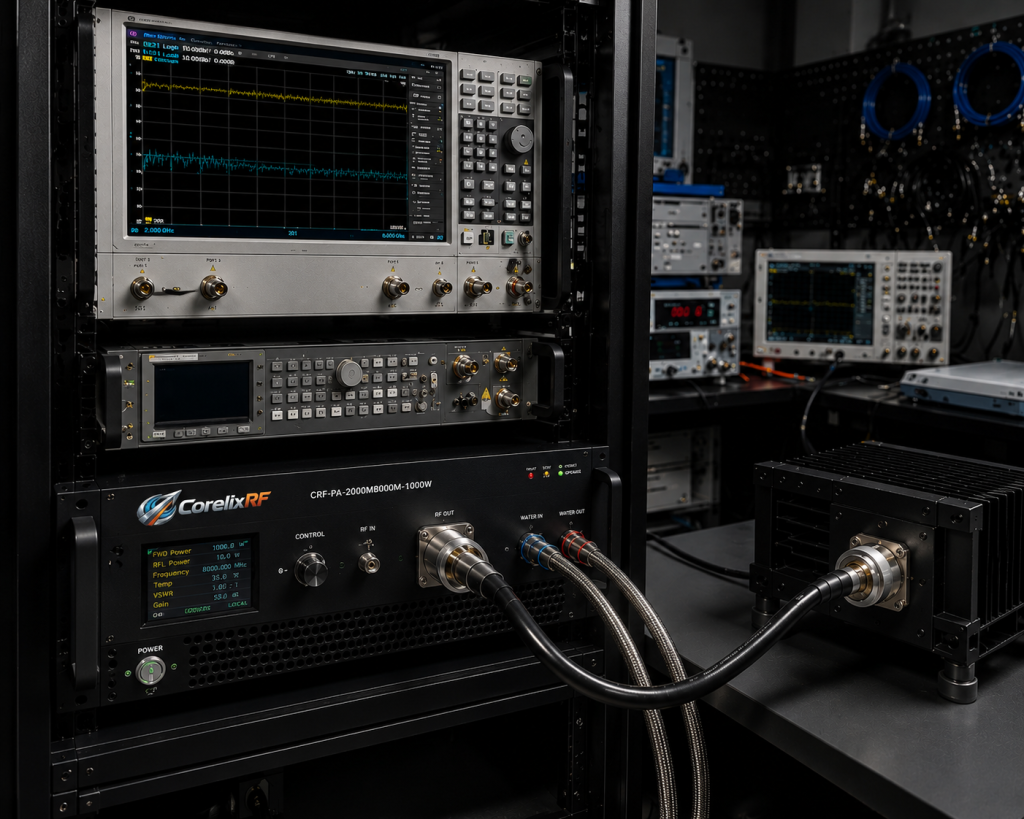
The source specification lists RS485/LAN control plus real-time temperature and current monitoring. These capabilities are useful when the amplifier is integrated into an automated test rack. At minimum, the control interface should support enable/disable, alarm reading, and state checks before RF drive is applied. If optional forward/reverse power monitoring is included, it can help detect load mismatch and incorrect setup before damage occurs.
Protection is not a substitute for good system design. Over-drive protection and alarm functions reduce risk, but the test script should still set conservative drive limits and verify that the load path is ready before enabling RF output. For many procurement teams, the control protocol review is just as important as the datasheet review.
Buying Checklist
A strong request for a 2-8 GHz broadband RF power amplifier includes frequency coverage, required output power at the load, duty cycle, expected operating time, source drive range, output interface, cooling preference, facility power, control interface, alarm-handling requirements, and acceptance-test points. If the project may need a different package, CorelixRF can review it as a custom RF amplifier request.
The broader RF power amplifier category is also useful when comparing 2-8 GHz against adjacent 2-6 GHz or 6-18 GHz platforms. Treat the amplifier as one part of the RF path, and the selection process becomes much more reliable.
FAQ
What is the focus keyword for this article?
The focus keyword is 2-8 GHz broadband RF power amplifier.
What CorelixRF model is referenced?
The article references CRF-PA-2000M8000M-1000W, a 2-8 GHz, 1000 W GaN SSPA platform.
Why choose liquid cooling?
Liquid cooling can help manage thermal load in high-power, long-duration, or compact installations, but it requires facility and maintenance planning.
What gain is listed in the source specification?
The referenced source specification lists 60 dB minimum small-signal gain.
Should a 2-6 GHz amplifier be considered instead?
Yes, if the project does not need operation above 6 GHz, a 2-6 GHz platform may simplify the requirement.