
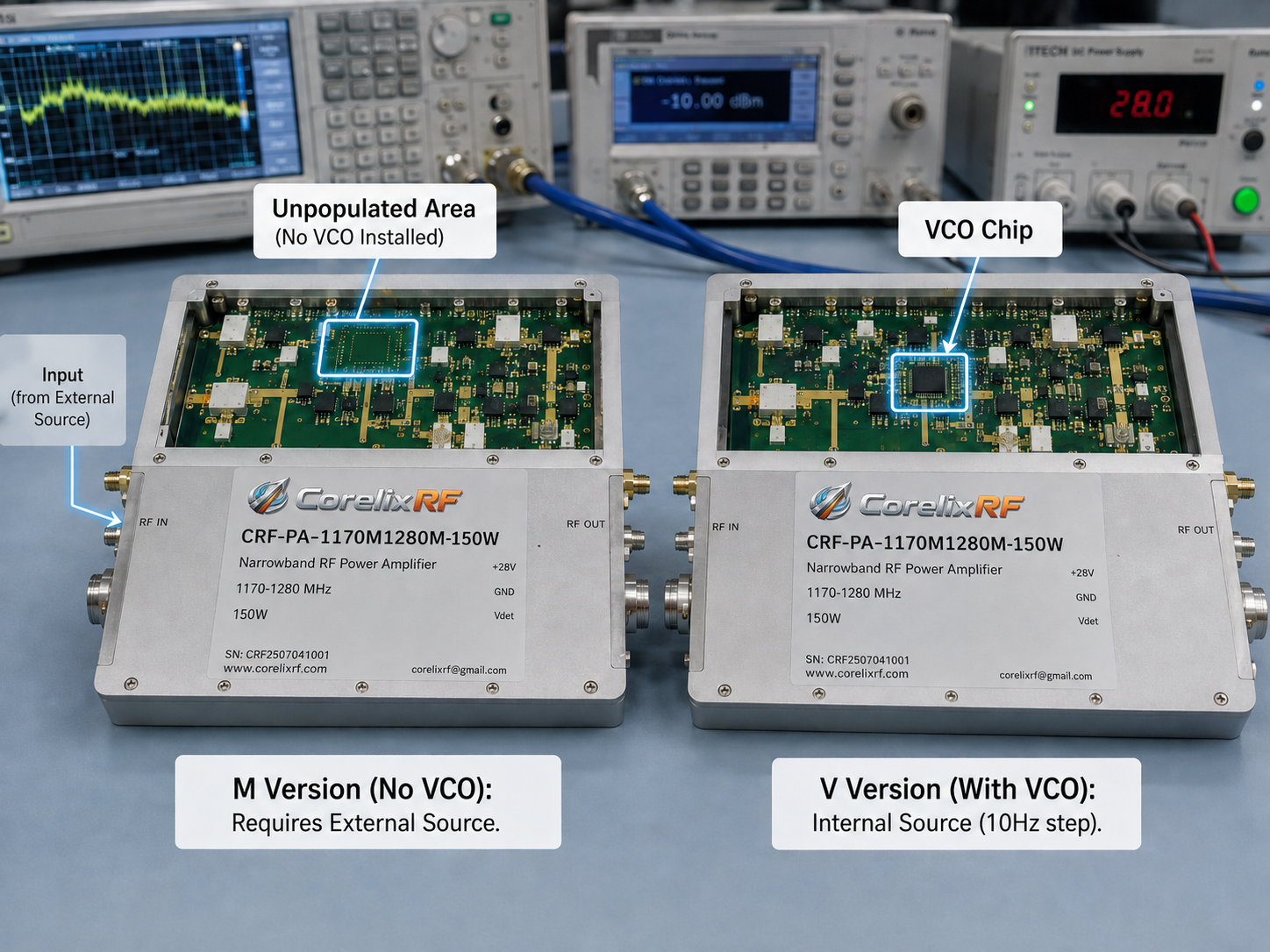
This article is written as a video-script style walkthrough. Instead of a conventional guide, it reads like a short technical demo for the CorelixRF CRF-PA-1170M1280M-150W, a narrowband RF power amplifier specified for 1170-1280 MHz operation, 150 W rated CW output power, third-generation GaN transistor technology, SMA-KFD46 RF connector information, and a 200 x 158 x 25 mm mechanical envelope.
Opening Shot: Product on the Bench
Narrator: Today we are looking at a dedicated L-band amplifier, not a general-purpose broadband RF power amplifier. The first question is whether the system really lives inside 1170-1280 MHz. If the answer is yes, a narrowband amplifier can simplify the RF design. If the frequency plan may expand, the buyer should compare other CorelixRF options before locking the specification.
Scene 1: Frequency Window
On screen: 1170-1280 MHz. Narrator: A narrowband model is selected when the channel group is known. It may help with output matching, filtering, gain planning, and thermal packaging. The tradeoff is flexibility. If tomorrow’s requirement moves outside the band, this product class may no longer be the right answer.
Scene 2: Output Power and Gain
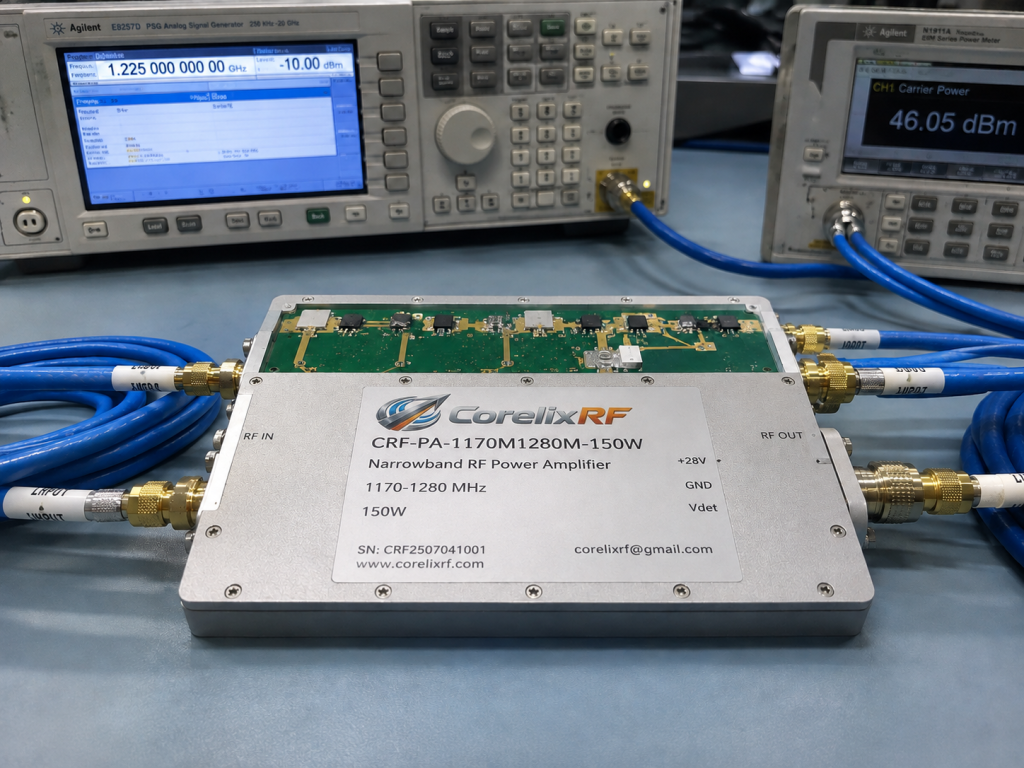
On screen: 150 W CW output. Narrator: The datasheet lists 150 W rated CW output power and gain values of 48, 50, and 52 dB for minimum, typical, and maximum conditions. Before enabling RF drive, compare source level, amplifier gain, downstream loss, and required power at the load. A model title is not a link budget.
Scene 3: M or V Configuration
On screen: M version and V version. Narrator: The datasheet notes an M version without internal VCO and a V version with an internal VCO source and 10 Hz stepping. This is not a minor option. It changes source architecture, calibration, troubleshooting, and software control. Choose the configuration that matches the system, not the one that sounds more complete.
Scene 4: Control and Protection
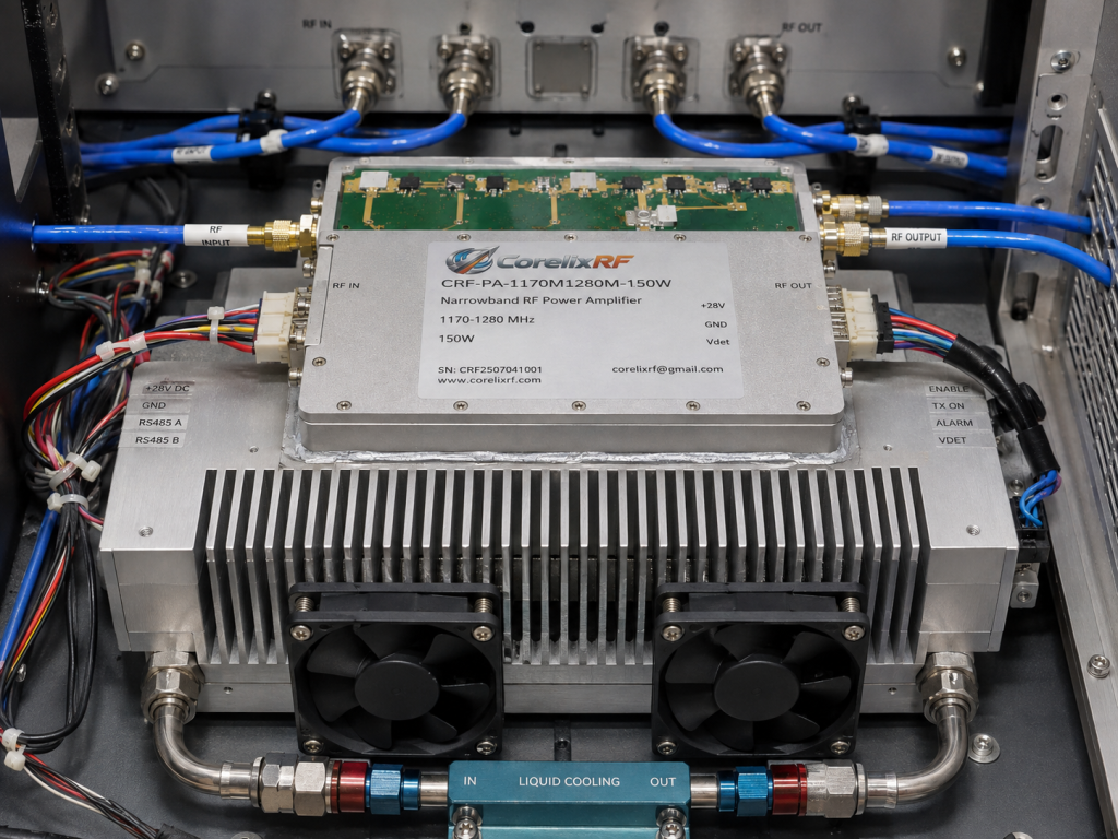
On screen: RS485, PA enable, protection. Narrator: RS485 monitoring/control, PA enable/disable control, external heat-sink cooling, and over-temperature, VSWR, voltage, and current protection define how the amplifier becomes part of a real system. These features should be mapped into the controller or operator workflow.
Scene 5: Mechanical and Thermal Close-Up
On screen: 200 x 158 x 25 mm envelope. Narrator: Compact does not mean thermally automatic. The heat sink, mounting surface, grounding, connector access, and harness routing should be reviewed before the enclosure is frozen. CW power needs a realistic thermal path.
Scene 6: Operator View
Narrator: A normal operator sequence might be: confirm frequency plan, select M or V configuration, check source level, confirm load condition, verify thermal readiness, enable the PA, watch status feedback, run the test, and shut down in the correct order. If any of those steps are unclear, the RFQ needs more detail.
When This Model Fits
CRF-PA-1170M1280M-150W can be reviewed for dedicated L-band RF channels, communications subsystem testing, controlled transmit paths, aerospace control benches, and fixture-level RF power where the system remains inside 1170-1280 MHz. If the project may expand beyond that range, compare the broader CorelixRF product range.
For deeper planning, review CorelixRF’s technical articles and consider whether a custom RF amplifier review is needed for packaging, control, or heat-sink requirements. This video-script format is meant to help a technical buyer picture the workflow, not only read the specification.
Closing Script
Narrator: Send CorelixRF the frequency plan, M or V preference, output target, waveform, duty cycle, input drive, heat-sink design, mounting orientation, available power, control-interface expectations, protection requirements, and acceptance-test needs. Attach a signal-path diagram if available.
Scene 7: What the Viewer Should Write Down
Narrator: Before the demo ends, write down the five decisions that affect fit: exact frequency plan, output power at the load, M or V configuration, thermal mounting, and control behavior. If any of those are unknown, the RFQ should say so. CorelixRF can review open items more effectively when uncertainty is explicit.
Scene 8: Common Misread
Narrator: A common mistake is reading 150 W as a complete system answer. It is not. The amplifier output must be compared with cable loss, filter loss, load condition, waveform, and duty cycle. The demo should show the power budget on screen because this is where many narrowband amplifier projects become either clean or confusing.
End Screen
On screen: send frequency plan, configuration preference, signal path, thermal plan, and control requirements to CorelixRF. Narrator: If the 1170-1280 MHz band is fixed and the system needs a 150 W CW narrowband stage, this model is worth a configuration review. If the band may change, start with the broader product range first.
For search visitors, the video-script structure helps because it mirrors how engineers evaluate hardware visually: identify the product, read the frequency label, follow the signal path, check controls, inspect cooling, and then ask what information is still missing. That is different from a checklist or RFQ template, even though the same datasheet facts remain in use.
FAQ
What is the CRF-PA-1170M1280M-150W frequency range?
The datasheet lists 1170-1280 MHz operation.
How much output power is listed?
The model is specified with 150 W rated CW output power.
What is the M versus V configuration note?
The M version is described without internal VCO, while the V version includes an internal VCO source and 10 Hz stepping.
Is this a broadband amplifier?
No. It is a narrowband amplifier for a defined 1170-1280 MHz range.