
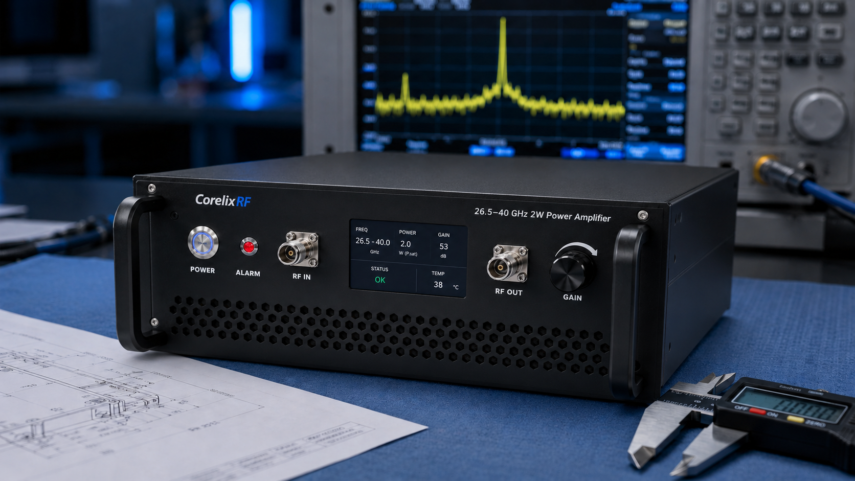
This selection guide uses CRF-PA-26500M40000M-2W as a verified CorelixRF example for engineers comparing Ka-band amplifier options. The model is taken from the local datasheet at D:/CorelixRF/功放/CW Solid-State RF Amplifiers/26.5G-40G/规格书/CRF-PA-26500M40000M-2W.docx, where it is identified as a 26.5 GHz to 40 GHz, 2 W solid-state RF power amplifier. The goal here is practical selection: when this class of amplifier is useful, what must be checked before purchase, and what information should be sent to CorelixRF for review.
Start With the Job, Not the Part Number
A mmWave RF amplifier is rarely selected by frequency and power alone. The actual job may be component characterization, receiver blocking, front-end stress testing, radar subsystem work, frequency-extension testing, or a compact Ka-band bench. Each job changes how much gain margin, connector repeatability, calibration access, and thermal margin are needed.
For CRF-PA-26500M40000M-2W, the headline fit is 26.5 GHz to 40 GHz coverage with 2 W output power. That can be attractive when the test needs moderate RF power in the 26.5-40 GHz region without moving immediately to a larger high-power cabinet. The selection question is whether 2 W at the amplifier output is enough after adapter loss, fixture loss, coupler loss, and calibration uncertainty.
Selection Criteria
Frequency span
Confirm whether the test uses the full 26.5 GHz to 40 GHz range or only several channels. A full-band sweep needs different confidence than a fixed-frequency bench.
Power at the device under test
Build a loss budget from the amplifier port to the actual load. Include waveguide transitions, coax adapters, couplers, switches, and safety margins.
Gain and drive
The source must drive the amplifier cleanly without accidental overdrive. Ask CorelixRF how gain control and input limits should be handled for the final configuration.
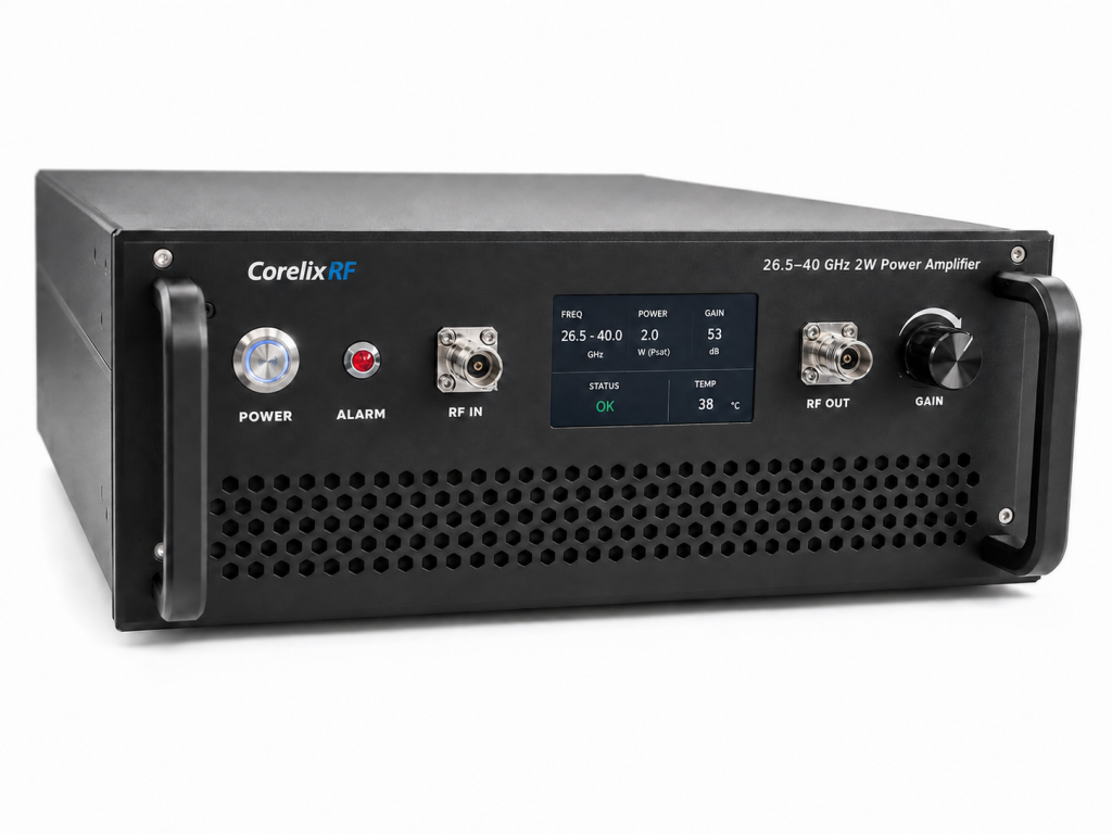
Mechanical fit
At Ka-band, connector access and cable routing matter. Leave enough space for torque tools, adapters, and measurement access.
When to Shortlist CRF-PA-26500M40000M-2W
- The required band sits inside 26.5 GHz to 40 GHz.
- The test requires around 2 W at the amplifier output before downstream losses.
- The project benefits from a GaN RF amplifier platform.
- The bench needs a compact RF path rather than an oversized high-power rack.
- The team can define calibration plane, connector path, duty cycle, and protection behavior.
Common Mistakes
The first mistake is asking only for price. The second is assuming output power at the amplifier port equals delivered power at the DUT. The third is ignoring thermal and mechanical access until the final integration stage. A better RFQ describes the waveform, duty cycle, load, connector path, control interface, and cooling condition at the same time as frequency and power.
Selection Trade-Offs
The strongest reason to choose this class of amplifier is focused Ka-band coverage with a modest power level. That can simplify a bench where the project needs controlled RF stress or component characterization but does not need a large cabinet amplifier. The trade-off is that the delivered power must be calculated carefully, because adapters and fixtures at Ka-band can consume a meaningful part of the budget.
Another selection trade-off is flexibility versus optimization. A broader amplifier may support more experiments, while a narrower or custom design may be easier to integrate into a defined system. For this model, the practical path is to shortlist it only after the engineering team has written down the required channels, load condition, connector path, and expected operating time.
Buyer Notes
Buyers should avoid treating the model as a simple commodity part. Ask for the final mechanical drawing, connector details, control options, and any project-specific test data that CorelixRF can provide. Also confirm whether the project needs documentation for internal qualification, incoming inspection, or acceptance testing. These details help prevent a technically correct amplifier from being difficult to approve internally.
Decision Matrix
Score the option against five factors: frequency fit, delivered power margin, mechanical fit, control readiness, and test documentation. A high score means the amplifier can move to quotation review. A low score does not mean the model is wrong; it means the project needs more detail before procurement can compare options. This approach keeps selection disciplined and avoids choosing a part only because the headline frequency and power look close.
For a compact Ka-band setup, the decision matrix should also include measurement repeatability. If the bench uses frequent adapter changes, the uncertainty budget may be larger than expected. If the bench is fixed and well calibrated, the same amplifier may be easier to qualify. That distinction should be visible before the RFQ is sent.
Selection Summary
In summary, the selection-guide style should leave the reader with a ranked decision, not just a description. Choose this model when the band, power level, mechanical format, and bench risk all align. Hold the decision when the RF path loss is unknown, when the load condition is unstable, or when the project has not defined how the amplifier will be controlled and protected. That simple go, hold, or customize framework makes the article different from a normal product overview.
FAQ
Is CRF-PA-26500M40000M-2W verified?
Yes. The model comes from the local CorelixRF datasheet path listed above.
Is this only for Ka-band testing?
It is most relevant where the 26.5 GHz to 40 GHz range matches the test plan, including Ka-band and nearby mmWave work.
What should I send with an RFQ?
Send frequency range, target load power, waveform, source drive, connector path, cooling condition, and control needs.
Can CorelixRF review a different package?
Yes. Use a custom RF amplifier review when mechanical or interface constraints differ from the standard configuration.
Next Step
Use this guide to decide whether CRF-PA-26500M40000M-2W belongs on your shortlist, then send the operating conditions to CorelixRF for confirmation.