
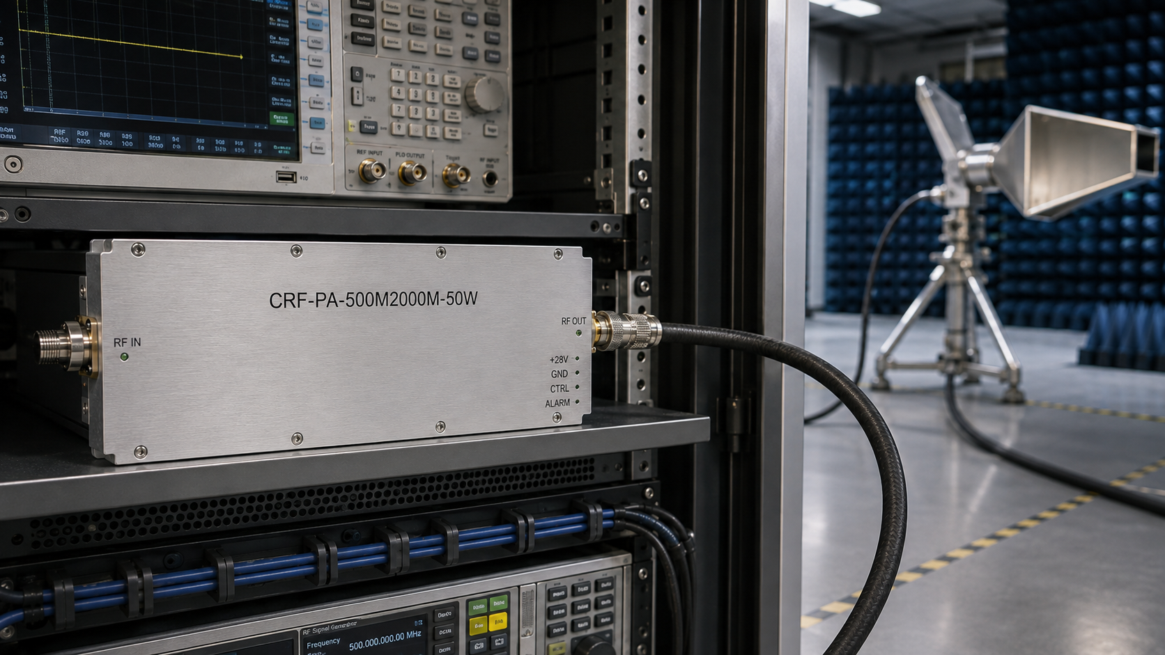
Gain horn antenna mounts affect RF test repeatability because they determine whether the antenna position, polarization, height, and boresight angle stay consistent from one run to the next. For 500 MHz to 2 GHz work, the CorelixRF CRF-PA-500M2000M-50W provides a useful amplifier reference point: 50 W rated output power, 47 dB minimum gain, -3 dB to +3 dB gain flatness, SMA-F input, N-F output, RS485 / LAN control, and a 19-inch 3U air-cooled rack-mount form factor.
This article is written as a specification checklist for engineers building repeatable RF power test setups. It connects the mechanical mount, the antenna, and the amplifier as one test path rather than treating the mount as a simple accessory. For related amplifier context, review CorelixRF’s RF power amplifier resources and the UHF RF amplifier page.
Start With the Test Geometry
The first mount decision is geometry. Define the distance from antenna phase center to device under test, the required height range, the azimuth and elevation adjustment range, and the polarization positions that must be repeated. If the test setup changes between horizontal and vertical polarization, the mount should allow repeatable rotation without moving the antenna center more than the uncertainty budget allows.
Mount Specification Checklist
- Frequency use case: 500 MHz to 2 GHz RF testing with amplifier margin.
- Amplifier anchor: CRF-PA-500M2000M-50W, 50 W rated output power.
- Gain budget: 47 dB minimum amplifier gain plus cable and fixture loss.
- RF connectors: SMA-F input and N-F output on the amplifier front panel.
- Control: RS485 / LAN for test bench integration.
- Power and cooling: AC 220 V, 300 W typical consumption, air cooling.
- Mechanical: 19-inch 3U rack-mount, 16 kg amplifier weight.
Why the Amplifier Matters to the Mount
A mount that is mechanically stable but poorly matched to the RF power path can still create inconsistent results. Cable routing from the amplifier output to the horn should avoid strain on the antenna flange or coax connector. The mount should also leave room for attenuators, couplers, adapters, or absorptive fixtures used during setup verification.
When a test plan extends into lower microwave bands, compare the 2-6 GHz RF power amplifier platform. If the fixture must support pulsed operation, the pulsed RF amplifier category may be a better planning reference.
Alignment Workflow
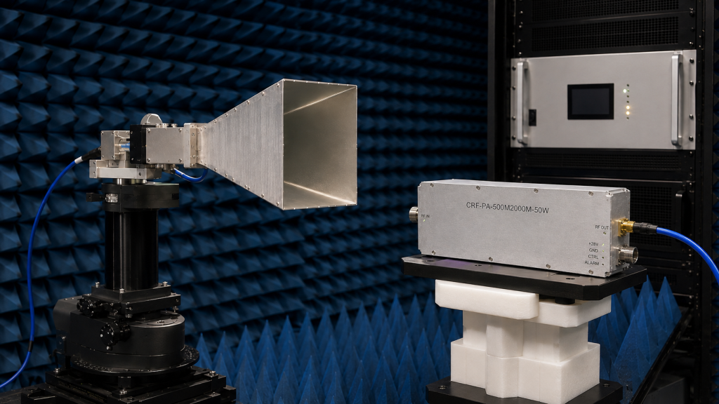
Use a repeatable alignment workflow instead of visual placement alone. Mark the mount base position, record the antenna height, document polarization, confirm connector torque policy, then verify forward power after the cable and before the antenna where practical. If the test environment uses a chamber, also document absorber clearance and cable routing.
Common Mounting Errors
The most common errors are letting a heavy cable pull the horn off-axis, changing antenna height between runs, placing the amplifier too far from the antenna without accounting for cable loss, and failing to record polarization. These are not amplifier faults, but they can make amplifier output look inconsistent at the measurement point.
Acceptance Notes for Repeatable Setup
A practical acceptance note should record the mount type, antenna model, polarization, height, distance, amplifier model, cable length, cable type, connector adapters, and measurement reference point. For the CRF-PA-500M2000M-50W, the RFQ should also include whether the 50 W output is required continuously at the amplifier output or after the antenna feed path. If the result must be compared across multiple runs, keep the same cable routing and avoid moving the amplifier rack between setups.
The mount should support the actual antenna weight with margin, but stiffness is more important than static load capacity alone. A mount that slowly drifts under cable tension can change alignment even if it never tips over. For repeatable engineering work, specify lockable azimuth, lockable elevation, stable height adjustment, and a documented reference mark for the antenna centerline. These details make the amplifier output easier to interpret because the mechanical setup is no longer an uncontrolled variable.
What to Send CorelixRF
Send the target frequency range, antenna type, expected field level or power target, cable length, connector stack, test distance, waveform, duty cycle, amplifier control preference, and any chamber or fixture drawings. If the setup requires a different output connector, power level, or rack format, include that early so CorelixRF can review whether a standard amplifier or a custom RF amplifier path is more appropriate.

Bench Record Template
A useful bench record can be simple: record the amplifier serial or model reference, gain setting, source level, cable part number, antenna mount height, antenna polarization, distance, ambient temperature, and operator notes. Add photographs to the internal lab record if your process allows it, but keep the public article focused on the engineering workflow. When the same mount position and amplifier settings are reused, engineers can separate true RF behavior from mechanical setup variation.
If the goal is procurement, include whether the mount must support multiple horn antennas or one fixed antenna. Multi-antenna fixtures need repeatable adapters and clear centerline references. A single-purpose mount can be simpler, but it still needs enough stiffness and adjustment control to prevent drift during high-power testing.
FAQ
Do gain horn antenna mounts affect RF power readings?
Yes. Position, polarization, cable strain, and antenna alignment can all change measured field or received power.
Why use CRF-PA-500M2000M-50W as the amplifier reference?
It provides 500 MHz to 2 GHz coverage, 50 W rated output power, RS485 / LAN control, and rack-mount integration for repeatable bench work.
Should the mount be selected before the amplifier?
No. Mount, antenna, amplifier, cable, and fixture requirements should be reviewed as one RF path.
Where should custom requirements be sent?
Use the CorelixRF Contact page with frequency range, power target, antenna type, cable path, and fixture constraints.