The primary difference between directional and omnidirectional antennas lies in their signal propagation focus; directional antennas concentrate RF energy in a specific path for long-range targeting, while omnidirectional variants broadcast signals equally in all horizontal positions to provide full 360-degree coverage. Imagine an engineer setting up a critical perimeter defense network. Suddenly, unauthorized drone systems appear on the radar, yet the countermeasure signal fails because of bad antenna selection, leaving your entire facility completely exposed. Finding the perfect balance between broad surveillance and focused suppression can become a massive headache when your communication links drop under pressure. Deploying high-performance Directional and Omnidirectional Antennas fixes these critical coverage vulnerabilities by delivering reliable multi-band tracking alongside immediate long-distance threat isolation.
Connect antenna coverage choices to RF hardware review
When directional or omnidirectional coverage affects amplifier sizing, antenna gain, cable loss, enclosure layout or RF front-end matching, CorelixRF can review the full RF path before procurement.
What Are Omnidirectional Antenna Core Dynamics?
Omnidirectional antenna systems broadcast electromagnetic power equally across all horizontal directions to create a complete donut-shaped coverage zone. Incorporating these robust systems into your layout guarantees that your receivers maintain constant contact with moving targets without requiring mechanical rotation mechanisms, making them a premier choice for baseline situational awareness. Many field engineers deploy these configurations when setting up broad mobile command centers where the exact location of incoming RF traffic remains completely unpredictable. Modern tactical operations rely heavily on high-power Directional and Omnidirectional Antennas to maintain stable communication perimeters across complex geographic landscapes.
How Do Omnidirectional Designs Radiate?
Horizontal radiation patterns distribute RF energy uniformly across a full 360-degree radius while minimizing vertical beamwidth. Here is the truth. You can visualize this radiation profile as a flattened sphere that extends far outward along the horizon but offers limited vertical overhead coverage.
- Broad 360-degree horizontal azimuth coverage
- Restricted vertical elevation beamwidth
- Continuous signal availability for mobile nodes
What Are Typical Omni Form Factors?
Common structural form factors include rubber duck, whip, and fiberglass collinear designs engineered for harsh industrial environments. Think about it. Selecting a rugged fiberglass collinear model provides excellent structural longevity alongside consistent electrical performance during prolonged outdoor deployments.
- High impact resistance in tactical zones
- Sealed weatherproofing for marine setups
- Key Takeaway: Utilizing collinear omni designs allows your technical staff to secure a reliable horizontal baseline network across wide operational fields.
| Antenna Type | Horizontal Coverage | Common Application |
| Collinear Omni | 360 Degrees | Base Station Broadcast |
| Tactical Whip | 360 Degrees | Mobile Manpack Radio |
Reviewing this data highlights how specific form factors serve distinct operational needs across broad security networks.
How Do Directional RF Systems Concentrate Signals?
Directional RF systems concentrate their entire electromagnetic output into a narrow, focused beam to maximize signal distance and penetration. By restricting the radiation angle, these specialized modules amplify transmission power toward a specific target, which drastically reduces interference from surrounding electronic noise sources. This focused approach makes them incredibly valuable for point-to-point backhaul links and targeted electronic countermeasures where maximum power delivery is mandatory. Integrating advanced Directional and Omnidirectional Antennas into your security architecture allows your team to achieve unparalleled range while isolating critical signal paths from external disruption.
Why Does Beamwidth Matter Most?
Narrower beamwidths yield higher forward gain by grouping the available radio frequency energy into a tight spatial sector. But here’s the kicker. When you decrease the beamwidth to less than fifteen degrees, your system gains immense tracking precision but demands highly accurate mechanical or electronic alignment.
- Exponential increase in forward signal range
- Drastic reduction in side-channel interference
- High tracking precision for dynamic targets
What Are Common Directional Architectures?
Standard directional architectures include Yagi-Uda, panel, parabolic dish, and periodic log structures tailored for specific frequency bandwidths. You might be wondering which architecture fits your tactical setup best. Choosing a high-power panel array offers a great balance between wind resistance and high forward gain for permanent outdoor installations.
- Parabolic dishes for deep-space telemetry
- Yagi arrays for structural simplicity
- Key Takeaway: Deploying panel arrays gives your engineers the ability to establish high-throughput point-to-point links over exceptional distances.
| Architecture | Relative Gain | Beamwidth Type |
| Parabolic Dish | Very High | Ultra-Narrow |
| Patch Panel | Medium-High | Medium Sector |
Examining these architectural metrics helps technical procurement officers pick the exact module needed for focused long-range signal delivery.
What Distinguishes Directional and Omnidirectional Antennas?
The core distinction between these two architectures centers on spatial coverage versus maximum signal distance. Omnidirectional models provide a wide safety net by scanning the entire local horizon simultaneously, whereas directional modules act as high-power spotlights that illuminate distant targets with extreme precision. Understanding this fundamental contrast helps system engineers avoid costly deployment errors that cause dead zones or weak signal states within critical perimeters. Balancing both Directional and Omnidirectional Antennas within a unified RF chain ensures your network remains adaptive to both close-range multi-target tracking and long-range point-to-point transmission needs.
How Do Gain Metrics Compare?
Directional options offer significantly higher passive gain ratings compared to their omnidirectional counterparts because of energy concentration. What’s the real story? Higher gain does not mean the antenna creates more power; it simply refocuses the existing signal energy more efficiently.
- Omni gain typically ranges from 2dBi to 9dBi
- Directional gain easily exceeds 12dBi to 24dBi
- Higher gain creates a narrower coverage footprint
Which Setup Reduces Signal Interference?
Directional designs inherently block out ambient electronic noise originating outside their specific forward radiation beamwidth. Ready for the good part? You can deploy these focused systems in heavily congested industrial environments without worrying about cross-channel degradation from neighboring radio transmitters.
- Passive spatial filtering discards off-axis noise
- Improved signal-to-noise ratio in crowded bands
- Key Takeaway: Implementing directional hardware allows your technical staff to maintain clean communication links in RF-polluted industrial zones.
| Attribute | Omnidirectional | Directional |
| Noise Rejection | Low Spatial Filtering | High Spatial Filtering |
| Coverage Area | Complete 360 Circle | Narrow Focused Wedge |
Analyzing these structural performance variations allows developers to select the ideal module configuration for complex spectrum conditions.
How Do Radiation Patterns Impact Field Deployment?
Radiation patterns dictate how an antenna interacts with its physical surroundings, determining both coverage shape and susceptibility to environmental obstacles. A proper understanding of these patterns prevents signal degradation caused by ground reflections, building obstructions, or terrain changes that disrupt standard wave propagation. Selecting the wrong radiation profile frequently leads to severe packet loss or total link failure during critical field operations. Integrating robust Directional and Omnidirectional Antennas with verified radiation plots enables your deployment teams to map out perfect signal perimeters before hardware installation begins.
What Is a 3D Radiation Plot?
A three-dimensional radiation plot visualizes both the horizontal azimuth and vertical elevation components of an antenna’s electromagnetic field. This is where it gets interesting. You can use these digital models to predict exactly how much signal energy will shoot into the sky or spill onto the ground.
- Azimuth plane displays horizontal distribution
- Elevation plane illustrates vertical signal height
- Sidelobes indicate secondary energy leakage points
How Do Sidelobes Affect Efficiency?
Sidelobes represent wasted electromagnetic energy radiating in unwanted directions outside the primary transmission beam. Look at this closely. Minimizing sidelobe levels helps protect your primary link from being intercepted or disrupted by malicious electronic actors.
- Sidelobe suppression prevents electronic eavesdropping
- Lower leakage increases main beam power density
- Key Takeaway: Selecting antennas with low sidelobe levels safeguards your data transmissions against external detection and signal jamming.
| Pattern Feature | Omni Antennas | Directional Antennas |
| Primary Lobe | Symmetric Donut | Focused Main Beam |
| Sidelobe Level | Negligible | Variable Based on Design |
Evaluating these specific radiation metrics ensures that your engineering team maximizes forward power while minimizing unintended signal spill.
When Should You Deploy Omnidirectional RF Networks?
Omnidirectional RF networks are ideal for applications demanding continuous 360-degree connectivity across rapidly moving or unpredictable transceiver nodes. These setups shine in urban security grids, mobile convoy communications, and local area base stations where maintaining a fixed physical alignment is entirely impossible. Relying on these omni configurations removes the need for complex tracking motorized mounts, which reduces overall hardware weight and deployment complexity. Utilizing premium Directional and Omnidirectional Antennas side by side provides your system with a comprehensive operational baseline that keeps mobile assets connected around the cloud.

How Do Omnis Support Fleet Management?
Mobile security fleets use omnidirectional vehicle mounts to maintain constant contact with command infrastructure while traversing rugged, twisting terrain. Here is the deal. As your vehicles turn and accelerate, the antenna maintains its broadcast link without suffering from orientation dropouts.
- Instantaneous tracking without mechanical lag
- Low-profile physical designs for vehicle roofs
- Multi-band support for diverse tactical radio sets
What Makes Omnis Great for Broadcast?
Base stations utilize high-gain omnidirectional towers to distribute local telemetry data over a wide area to multiple scattered receiver terminals. To be completely blunt. Trying to achieve this wide coverage using directional arrays would require a massive cluster of expensive panels and complex splitters.
- Simultaneous data delivery to infinite nodes
- Simplified single-cable tower installations
- Key Takeaway: Implementing a centralized omni tower dramatically lowers your initial infrastructure expenditures while covering every local quadrant simultaneously.
| Fleet Scenario | Recommended Omni Type | Main Benefit |
| Tactical Convoy | Low-Profile Mobile Whip | Shock-Resistant Link |
| Command Center | High-Gain Collinear Mast | Maximized Area Broadcast |
Reviewing these specific deployment scenarios highlights why omnidirectional solutions remain the benchmark for widespread area connectivity.
Where Do Directional Antennas Provide Better Reach?
Directional antennas provide superior reach in long-range point-to-point links and specialized security applications where signals must travel several miles without degradation. By focusing the available RF energy, these high-power modules pierce through thick atmospheric attenuation and localized electronic noise much better than any omnidirectional design can manage. This makes them the definitive choice for linking remote industrial sites, securing distant perimeters, or executing precise electronic countermeasures. Deploying custom Directional and Omnidirectional Antennas within your network topology ensures that long-range data corridors remain perfectly stable under challenging field conditions.
How Do Panels Secure Remote Links?
Fixed patch panels establish high-capacity backhaul channels between distant facilities without the massive expense of laying physical fiber-optic cables. Let that sink in. You can link two production facilities located ten miles apart using a pair of aligned high-gain panel systems.
- Elimination of expensive physical trenching costs
- High data throughput over multi-mile gaps
- Quick deployment timelines for rapid facility expansion
Why Use Directional Tracking Mounts?
Automated tracking mounts rotate directional arrays in real time to follow distant high-speed assets like aircraft or defense surveillance drones. The results speak for themselves. This combination delivers maximum signal power directly to the moving target over exceptional distances.
- Continuous target locking via signal feedback
- Dynamic optimization of forward antenna gain
- Key Takeaway: Combining directional hardware with automated tracking gives your operations continuous high-power telemetry across vast operational zones.
| Distance Range | Optimal Antenna Choice | Real-World Use Case |
| 1 to 5 Miles | High-Gain Patch Panel | Inter-Facility Link |
| 5+ Miles | Parabolic Dish System | Long-Range Telemetry |
Analyzing these long-distance options proves that directional hardware is unmatched when your business demands extreme range and pinpoint signal accuracy.
How Does Antenna Gain Influence Overall Coverage?
Antenna gain directly influences coverage by reshaping the geometry of the transmitted signal, trade-offs being made between distance and spatial angle. Increasing gain does not create extra radio frequency energy; instead, it compresses the signal pattern to send power further in a specific direction. Understanding this passive amplification mechanism allows system engineers to balance range requirements against spatial coverage limitations to prevent unintended network blind spots. Deploying premium Directional and Omnidirectional Antennas with appropriate gain ratings ensures your RF infrastructure matches your unique geographic field requirements.

What Are the High-Gain Pitfalls?
High-gain omnidirectional options compress the vertical beamwidth so severely that targets directly above or below the antenna lose connection completely. This is a major catch. If your tactical setup is located in a deep valley, an ultra-high-gain omni might shoot right over your mobile units.
- Extreme vertical compression limits mountain coverage
- High sensitivity to slight mast tilting errors
- Narrow overhead reception zones near the tower base
How Does dBi Predict Link Budgets?
The dBi rating measures antenna gain relative to an isotropic radiator, serving as a foundation for calculating accurate link budgets. Let us look at the facts. Adding a twelve dBi directional module to your transmitter can quadruple your effective radiated power without changing your power amplifier hardware.
- Standardized mathematical baseline for field calculations
- Direct correlation with maximum wireless distance
- Key Takeaway: Mastering gain metrics allows your engineering team to hit distance targets while keeping amplifier costs under control.
| Gain Rating | Signal Beam Profile | Ideal Topography |
| Low Gain (3 dBi) | Wide Spherical Shape | Hilly or Mountainous Terrain |
| High Gain (12 dBi) | Flat Compressed Disk | Flat Open Plains or Oceans |
Evaluating these gain trade-offs enables your technical procurement managers to specify the exact hardware configurations required for stable field communications.
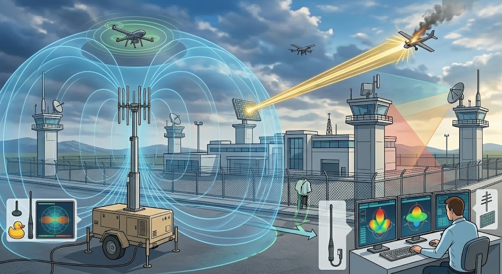
Why Do Counter-Drone Setups Require Both Types?
Counter-drone setups require both antenna types because modern threat mitigation demands simultaneous 360-degree detection and highly focused long-range signal disruption. Omnidirectional modules handle the initial detection phase by scanning the entire surrounding airspace for incoming unauthorized unmanned aerial systems. Once a threat is confirmed, directional arrays take over to blast targeted jamming signals directly at the drone, cutting its control link without disrupting local friendly communications. Blending these Directional and Omnidirectional Antennas into a single defense platform creates an impenetrable electronic perimeter around critical infrastructure sites.
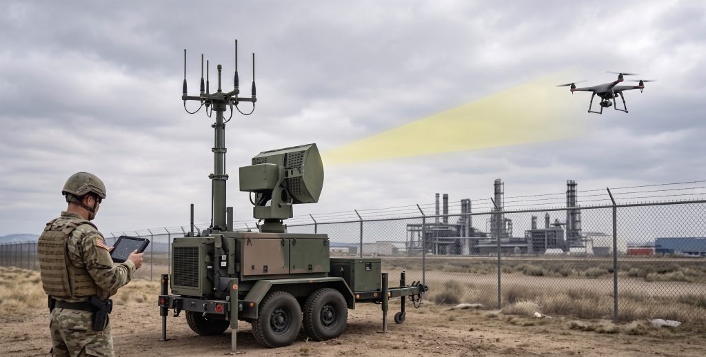
How Do Omnis Handle Threat Detection?
Omnidirectional detection arrays listen continuously across multiple frequency bands to catch drone telemetry signals the moment a target enters the local airspace. The reality is simple. Without this 360-degree radar or RF listening net, a stealthy drone could easily slip past your defenses from an unmonitored angle.
- Constant all-weather hemispherical surveillance coverage
- Immediate identification of incoming multi-frequency signals
- Seamless integration with centralized threat warning software
Why Is Directional Jamming Necessary?
Directional jamming modules deliver massive concentrated RF power to overwhelm the drone’s internal GPS or control receiver at long ranges. Here is the fascinating part. This concentrated burst forces the threat to land or return to its origin while keeping neighboring civilian networks completely operational.
- Concentrated suppression prevents wide-area spectrum pollution
- High-power density targets specific frequency channels
- Key Takeaway: Deploying focused directional disruption protects your facility while preventing collateral interference on nearby friendly communication systems.
| Defense Phase | Antenna Mechanism | Operational Goal |
| Detection Net | Broad Omnidirectional Scan | Early Warning & Triangulation |
| Neutralization | Focused Directional Burst | Targeted Threat Disruption |
Studying these integrated defense steps highlights how combining both architectural styles delivers total protection for sensitive military and industrial perimeters.
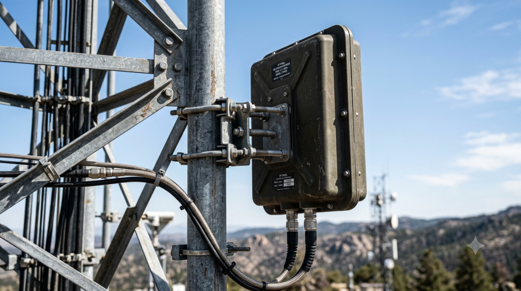
Can Weather Disturb Directional and Omnidirectional Antennas?
Weather conditions can severely disturb antenna performance by causing physical alignment shifts, signal attenuation, or structural damage to exposed outdoor installations. Heavy ice accumulation, torrential downpours, and high wind gusts can alter the electrical properties or physical pointing direction of high-frequency communication links. Protecting your hardware with rugged radomes and heavy-duty mounts prevents these environmental factors from degrading your long-term network reliability. Deploying ruggedized Directional and Omnidirectional Antennas built with military-grade sealing ensures your communications remain online during extreme weather anomalies.
How Does Rain Fade Impact Signals?
High-frequency radio signals suffer from rain fade when traveling through heavy downpours because water droplets absorb and scatter the electromagnetic energy. Keep this in mind. As operating frequencies climb past ten gigahertz, water absorption becomes a major threat to your long-distance point-to-point links.
- Signal scattering caused by atmospheric moisture droplets
- Increased path loss over multi-mile wireless links
- Requisite power margins to overcome wet conditions
Why Does Wind Load Threaten Alignment?
High winds exert massive physical pressure on large directional dish or panel assemblies, causing minute tracking misalignments that can drop narrow beams completely. What is the solution? Specifying low-wind-load panel profiles or heavy-duty brackets keeps your high-gain systems perfectly locked onto their targets during heavy storms.
- Physical torsion creates temporary signal drops
- Mechanical fatigue risks long-term structural failure
- Key Takeaway: Investing in low-wind-load physical antenna designs prevents storm-induced link dropouts and protects expensive tower infrastructure.
| Weather Element | Primary Impact | Best Preventive Measure |
| Heavy Rain | Atmospheric Signal Fade | Increase Power Amplifier Headroom |
| High Winds | Physical Antenna Misalignment | Deploy Rigid Heavy-Duty Mounts |
Analyzing these environmental threats enables your engineering staff to build robust, weatherproof wireless networks that withstand the harshest outdoor climates.
How Do You Select the Proper Antenna Infrastructure?
Selecting the proper antenna infrastructure requires a detailed analysis of your specific operational range, surrounding spectrum congestion, and deployment mobility constraints. Your engineering team must carefully weigh whether your system requires wide-area coverage or focused long-distance connectivity to choose the exact module that maximizes mission success. Making a hasty choice without studying field topography often leads to poor data throughput, dropped links, or total communication failure under pressure. Evaluating premium Directional and Omnidirectional Antennas alongside high-efficiency power amplifiers enables your enterprise to construct a highly reliable, military-grade RF chain.
What Role Does Frequency Play?
Operating frequencies dictate the physical size of your antenna elements and determine how well your signals penetrate buildings or foliage. Here is the bottom line. Lower frequencies offer great obstacle penetration but need larger physical structures, whereas high-frequency systems are compact but suffer from line-of-sight limitations.
- Lower frequencies give superior signal penetration
- Higher frequencies allow compact hardware profiles
- Strict line-of-sight requirements for microwave bands
How Do You Evaluate Supplier Quality?
Evaluating supplier quality requires looking beyond raw spec sheets to examine actual production testing protocols, material certifications, and environmental validation standards. This is what separates the best. Partnering with a manufacturer that utilizes a rigorous multi-step testing protocol guarantees that every module performs flawlessly in extreme field environments.
- Strict adherence to international ISO standards
- Verifiable environmental stress and vibration testing
- Deep engineering support from design to manufacturing
- Key Takeaway: Choosing a supplier with proven multi-phase validation processes ensures your long-term contracts receive reliable, zero-defect hardware.
| Selection Criteria | Omnidirectional Focus | Directional Focus |
| Target Mobility | High (Scattered Assets) | Low (Fixed or Tracked Nodes) |
| Range Expectation | Short to Medium Distances | Extended Long-Range Gaps |
Reviewing these technical selection benchmarks assists corporate procurement teams in sourcing the perfect RF hardware for mission-critical industrial applications.
Summary of RF Antenna Integration
Navigating the complex choices between directional and omnidirectional wireless hardware requires a deep understanding of spatial radiation patterns, gain trade-offs, and environmental field conditions. This comprehensive analysis has addressed your core design challenges, helping your technical teams choose between wide 360-degree field surveillance and focused long-distance signal transmission. Our production facility stands ready to provide your enterprise with high-efficiency wideband GaN amplifiers, advanced digital signal sources, and custom antenna arrays built for extreme environments. To secure your communication infrastructure against modern threats and optimize your system-level performance, contact us today to receive an expert engineering proposal within twenty-four hours. We are dedicated to pioneering next-generation military-grade RF chain architectures that safeguard critical assets and empower system integrators worldwide.
Frequently Asked Questions
- Q1: Can I combine both antenna types into a single counter-drone field system?Yes, you absolutely can. Integrating both variants allows your security setup to use omni modules for initial 360-degree threat detection and directional arrays for high-power targeted signal suppression.
- Q2: What’s the best antenna choice for a fast-moving tactical vehicle convoy?An omnidirectional mobile whip antenna is the optimal selection. This choice guarantees continuous communication across changing directions without needing complex motorized tracking mounts that can fail in rugged terrain.
- Q3: How do I know if my link budget requires a high-gain directional panel?You will know by calculating your target link distance and measuring local electronic noise levels. If your signal must travel several miles or pierce through heavy industrial interference, a high-gain panel is mandatory to maintain link stability.
- Q4: Can heavy rain completely drop my high-frequency directional link?Yes, it certainly can under specific conditions. High-frequency signals past ten gigahertz suffer from severe rain fade because water droplets scatter RF energy, demanding extra power headroom to prevent total dropouts.
- Q5: How do I know if an omni antenna gain is too high for my hilly terrain setup?You can tell by analyzing the vertical elevation plot of the antenna. High-gain omnis compress the vertical beam so tightly into a flat disk that units operating down in deep valleys or up on ridges will lose coverage entirely.